

16
2 Electrodynamics at Interface
z
t
l
(a, c)
z
t
l
(b, d)
A
S
^
^
^
^
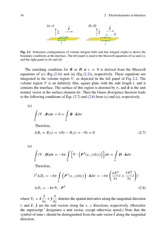
Fig. 2.2 Schematic configurations of volume integral (left) and line integral (right) to derive the
boundary conditions at the interface. The left panel is used to the Maxwell equations of (a) and (c),
and the right panel to (b) and (d)
The matching condition for B or D at z = 0 is derived from the Maxwell
equations of (c) (Eq. (2.4)) and (a) (Eq. (2.2)), respectively. These equations are
integrated in the volume region V , as depicted in the left panel of Fig. 2.2. The
volume region V is an infinitely thin, square plate with the side length l, and it
contains the interface. The surface of this region is denoted by σ , and ˆ
n is the unit
normal vector at the surface element dσ . Then the Gauss divergence theorem leads
to the following conditions of Eqs. (2.7) and (2.8) from (c) and (a), respectively.
(c)
V
(∇ · B)dr = 0 =
σ
B · ˆ
ndσ
Therefore,
B z = B z (z = +0) − B z (z = −0) = 0
(2.7)
(a)
V
(∇ · D)dr = −4π
V
∇ ·
P
S (x, y)δ(z)
dr =
σ
D · ˆ
ndσ
Therefore,
l
2 D z = −4π
σ
P
S (x, y)δ(z)
· ˆ
ndσ = −4π
∂P S
x
∂x
l +
∂P S
y
∂y
l
l
D z = −4π ∇ t · P
S
(2.8)
where ∇ t = ˆ
x
∂
∂x
+ ˆ
y
∂
∂y
denotes the spatial derivative along the tangential direction
t, and ˆ
x, ˆ
y are the unit vectors along the x, y directions, respectively. (Hereafter
the superscript ˆ designates a unit vector, except otherwise noted.) Note that the
symbol of time t should be distinguished from the unit vector ˆ
t along the tangential
direction.
2 Electrodynamics at Interface
z
t
l
(a, c)
z
t
l
(b, d)
A
S
^
^
^
^
Fig. 2.2 Schematic configurations of volume integral (left) and line integral (right) to derive the
boundary conditions at the interface. The left panel is used to the Maxwell equations of (a) and (c),
and the right panel to (b) and (d)
The matching condition for B or D at z = 0 is derived from the Maxwell
equations of (c) (Eq. (2.4)) and (a) (Eq. (2.2)), respectively. These equations are
integrated in the volume region V , as depicted in the left panel of Fig. 2.2. The
volume region V is an infinitely thin, square plate with the side length l, and it
contains the interface. The surface of this region is denoted by σ , and ˆ
n is the unit
normal vector at the surface element dσ . Then the Gauss divergence theorem leads
to the following conditions of Eqs. (2.7) and (2.8) from (c) and (a), respectively.
(c)
V
(∇ · B)dr = 0 =
σ
B · ˆ
ndσ
Therefore,
B z = B z (z = +0) − B z (z = −0) = 0
(2.7)
(a)
V
(∇ · D)dr = −4π
V
∇ ·
P
S (x, y)δ(z)
dr =
σ
D · ˆ
ndσ
Therefore,
l
2 D z = −4π
σ
P
S (x, y)δ(z)
· ˆ
ndσ = −4π
∂P S
x
∂x
l +
∂P S
y
∂y
l
l
D z = −4π ∇ t · P
S
(2.8)
where ∇ t = ˆ
x
∂
∂x
+ ˆ
y
∂
∂y
denotes the spatial derivative along the tangential direction
t, and ˆ
x, ˆ
y are the unit vectors along the x, y directions, respectively. (Hereafter
the superscript ˆ designates a unit vector, except otherwise noted.) Note that the
symbol of time t should be distinguished from the unit vector ˆ
t along the tangential
direction.