

13 Spinoptics in Plasmonics
481
0.
0
0
. 5
1 . 0
0.0
0.2
0.4
Amplitude (a.u.)
sp
x λ
/
nm
250
x
E
y
E
z
E
±
σ
+
σ
−
σ
0
1
π
π
−
(b)
(a)
( c)
(d)
(e)
nm
500
x
y
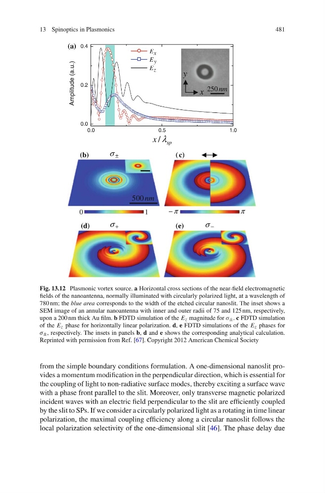
Fig. 13.12 Plasmonic vortex source. a Horizontal cross sections of the near-field electromagnetic
fields of the nanoantenna, normally illuminated with circularly polarized light, at a wavelength of
780 nm; the blue area corresponds to the width of the etched circular nanoslit. The inset shows a
SEM image of an annular nanoantenna with inner and outer radii of 75 and 125 nm, respectively,
upon a 200 nm thick Au film. b FDTD simulation of the E z magnitude for λ ± . c FDTD simulation
of the E z phase for horizontally linear polarization. d, e FDTD simulations of the E z phases for
λ ± , respectively. The insets in panels b, d and e shows the corresponding analytical calculation.
Reprinted with permission from Ref. [67]. Copyright 2012 American Chemical Society
from the simple boundary conditions formulation. A one-dimensional nanoslit provides a momentum modification in the perpendicular direction, which is essential for
the coupling of light to non-radiative surface modes, thereby exciting a surface wave
with a phase front parallel to the slit. Moreover, only transverse magnetic polarized
incident waves with an electric field perpendicular to the slit are efficiently coupled
by the slit to SPs. If we consider a circularly polarized light as a rotating in time linear
polarization, the maximal coupling efficiency along a circular nanoslit follows the
local polarization selectivity of the one-dimensional slit [46]. The phase delay due
481
0.
0
0
. 5
1 . 0
0.0
0.2
0.4
Amplitude (a.u.)
sp
x λ
/
nm
250
x
E
y
E
z
E
±
σ
+
σ
−
σ
0
1
π
π
−
(b)
(a)
( c)
(d)
(e)
nm
500
x
y
Fig. 13.12 Plasmonic vortex source. a Horizontal cross sections of the near-field electromagnetic
fields of the nanoantenna, normally illuminated with circularly polarized light, at a wavelength of
780 nm; the blue area corresponds to the width of the etched circular nanoslit. The inset shows a
SEM image of an annular nanoantenna with inner and outer radii of 75 and 125 nm, respectively,
upon a 200 nm thick Au film. b FDTD simulation of the E z magnitude for λ ± . c FDTD simulation
of the E z phase for horizontally linear polarization. d, e FDTD simulations of the E z phases for
λ ± , respectively. The insets in panels b, d and e shows the corresponding analytical calculation.
Reprinted with permission from Ref. [67]. Copyright 2012 American Chemical Society
from the simple boundary conditions formulation. A one-dimensional nanoslit provides a momentum modification in the perpendicular direction, which is essential for
the coupling of light to non-radiative surface modes, thereby exciting a surface wave
with a phase front parallel to the slit. Moreover, only transverse magnetic polarized
incident waves with an electric field perpendicular to the slit are efficiently coupled
by the slit to SPs. If we consider a circularly polarized light as a rotating in time linear
polarization, the maximal coupling efficiency along a circular nanoslit follows the
local polarization selectivity of the one-dimensional slit [46]. The phase delay due