

436
S. V. Boriskina
observed strong light focusing effects can be attributed to nanostructure-induced
formation and manipulation of optical powerflow vortices. Finally, I will discuss
application of these new design principles to the development of multi-functional
phase-operated plasmonic machinery, including light-trapping and biosensing platforms, SERS substrates, spectrally-tunable directional nanoantennas, strain sensors,
waveguides, and metamaterial building blocks.
12.2 Energy Transport and Dissipation in Plasmonic Materials
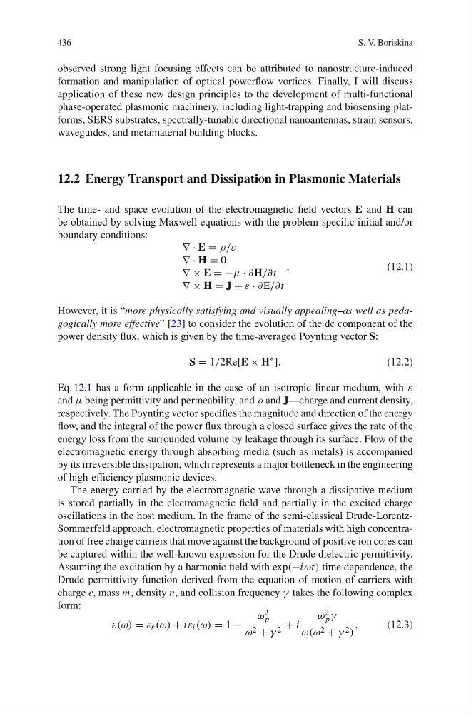
The time- and space evolution of the electromagnetic field vectors E and H can
be obtained by solving Maxwell equations with the problem-specific initial and/or
boundary conditions:
≈ · E = ε/λ
≈ · H = 0
≈ × E = −μ · πH/πt
≈ × H = J + λ · πE/πt
,
(12.1)
However, it is “more physically satisfying and visually appealing–as well as pedagogically more effective” [23] to consider the evolution of the dc component of the
power density flux, which is given by the time-averaged Poynting vector S:
S = 1/2Re[E × H
∼
].
(12.2)
Eq. 12.1 has a form applicable in the case of an isotropic linear medium, with λ
and μ being permittivity and permeability, and ε and J—charge and current density,
respectively. The Poynting vector specifies the magnitude and direction of the energy
flow, and the integral of the power flux through a closed surface gives the rate of the
energy loss from the surrounded volume by leakage through its surface. Flow of the
electromagnetic energy through absorbing media (such as metals) is accompanied
by its irreversible dissipation, which represents a major bottleneck in the engineering
of high-efficiency plasmonic devices.
The energy carried by the electromagnetic wave through a dissipative medium
is stored partially in the electromagnetic field and partially in the excited charge
oscillations in the host medium. In the frame of the semi-classical Drude-LorentzSommerfeld approach, electromagnetic properties of materials with high concentration of free charge carriers that move against the background of positive ion cores can
be captured within the well-known expression for the Drude dielectric permittivity.
Assuming the excitation by a harmonic field with exp(−iωt) time dependence, the
Drude permittivity function derived from the equation of motion of carriers with
charge e, mass m, density n, and collision frequency α takes the following complex
form:
λ(ω) = λ r (ω) + iλ i (ω) = 1 −
ω 2
p
ω 2 + α 2 + i
ω 2
p α
ω(ω 2 + α 2 )
,
(12.3)
S. V. Boriskina
observed strong light focusing effects can be attributed to nanostructure-induced
formation and manipulation of optical powerflow vortices. Finally, I will discuss
application of these new design principles to the development of multi-functional
phase-operated plasmonic machinery, including light-trapping and biosensing platforms, SERS substrates, spectrally-tunable directional nanoantennas, strain sensors,
waveguides, and metamaterial building blocks.
12.2 Energy Transport and Dissipation in Plasmonic Materials
The time- and space evolution of the electromagnetic field vectors E and H can
be obtained by solving Maxwell equations with the problem-specific initial and/or
boundary conditions:
≈ · E = ε/λ
≈ · H = 0
≈ × E = −μ · πH/πt
≈ × H = J + λ · πE/πt
,
(12.1)
However, it is “more physically satisfying and visually appealing–as well as pedagogically more effective” [23] to consider the evolution of the dc component of the
power density flux, which is given by the time-averaged Poynting vector S:
S = 1/2Re[E × H
∼
].
(12.2)
Eq. 12.1 has a form applicable in the case of an isotropic linear medium, with λ
and μ being permittivity and permeability, and ε and J—charge and current density,
respectively. The Poynting vector specifies the magnitude and direction of the energy
flow, and the integral of the power flux through a closed surface gives the rate of the
energy loss from the surrounded volume by leakage through its surface. Flow of the
electromagnetic energy through absorbing media (such as metals) is accompanied
by its irreversible dissipation, which represents a major bottleneck in the engineering
of high-efficiency plasmonic devices.
The energy carried by the electromagnetic wave through a dissipative medium
is stored partially in the electromagnetic field and partially in the excited charge
oscillations in the host medium. In the frame of the semi-classical Drude-LorentzSommerfeld approach, electromagnetic properties of materials with high concentration of free charge carriers that move against the background of positive ion cores can
be captured within the well-known expression for the Drude dielectric permittivity.
Assuming the excitation by a harmonic field with exp(−iωt) time dependence, the
Drude permittivity function derived from the equation of motion of carriers with
charge e, mass m, density n, and collision frequency α takes the following complex
form:
λ(ω) = λ r (ω) + iλ i (ω) = 1 −
ω 2
p
ω 2 + α 2 + i
ω 2
p α
ω(ω 2 + α 2 )
,
(12.3)