

406
A. Pors et al.
0.05
0.1
0.15
L 1 =125nm
d=100nm
d=120nm
d=140nm
800 900 1000 1100 1200 1300 1400 1500
0.05
0.1
0.15
0.2
λ (nm)
σ
ext (μm 2
)
d=120nm
L 1 =120nm
L 1 =125nm
L 1 =130nm
0
1
2
3
x 10
−31
|p
x
| (Cm)
λ (nm)
800 900 1000 1100 1200 1300 1400 1500
0
0.5
1
1.5
2
2.5
3
x 10
−23
|m
z | (Am
2
)
800 900 1000 1100 1200 1300 1400 1500
0
0.02
0.04
0.06
0.08
0.1
0.12
0.14
0.16
λ (nm)
σ (μm
2
)
scat (i)
ext (i)
scat (ii)
ext (ii)
scat (i+ii)
ext (i+ii)
z x
y
d
w
w
w
w=25nm
1 5 0 n m
L 1
(a)
(b)
(d)
(c)
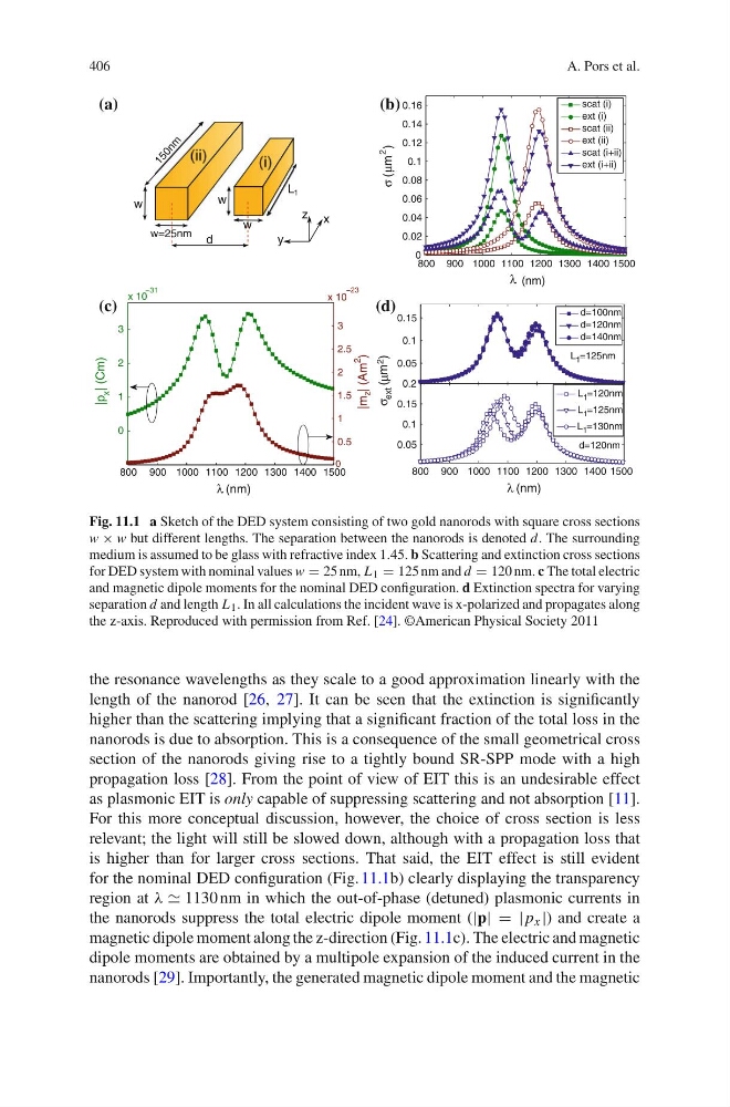
Fig. 11.1 a Sketch of the DED system consisting of two gold nanorods with square cross sections
w × w but different lengths. The separation between the nanorods is denoted d. The surrounding
medium is assumed to be glass with refractive index 1.45. b Scattering and extinction cross sections
for DED system with nominal values w = 25 nm, L 1 = 125 nm and d = 120 nm. c The total electric
and magnetic dipole moments for the nominal DED configuration. d Extinction spectra for varying
separation d and length L 1 . In all calculations the incident wave is x-polarized and propagates along
the z-axis. Reproduced with permission from Ref. [24]. ©American Physical Society 2011
the resonance wavelengths as they scale to a good approximation linearly with the
length of the nanorod [26, 27]. It can be seen that the extinction is significantly
higher than the scattering implying that a significant fraction of the total loss in the
nanorods is due to absorption. This is a consequence of the small geometrical cross
section of the nanorods giving rise to a tightly bound SR-SPP mode with a high
propagation loss [28]. From the point of view of EIT this is an undesirable effect
as plasmonic EIT is only capable of suppressing scattering and not absorption [11].
For this more conceptual discussion, however, the choice of cross section is less
relevant; the light will still be slowed down, although with a propagation loss that
is higher than for larger cross sections. That said, the EIT effect is still evident
for the nominal DED configuration (Fig. 11.1b) clearly displaying the transparency
region at ϕ ∼ 1130 nm in which the out-of-phase (detuned) plasmonic currents in
the nanorods suppress the total electric dipole moment (|p| = |p x |) and create a
magnetic dipole moment along the z-direction (Fig. 11.1c). The electric and magnetic
dipole moments are obtained by a multipole expansion of the induced current in the
nanorods [29]. Importantly, the generated magnetic dipole moment and the magnetic
A. Pors et al.
0.05
0.1
0.15
L 1 =125nm
d=100nm
d=120nm
d=140nm
800 900 1000 1100 1200 1300 1400 1500
0.05
0.1
0.15
0.2
λ (nm)
σ
ext (μm 2
)
d=120nm
L 1 =120nm
L 1 =125nm
L 1 =130nm
0
1
2
3
x 10
−31
|p
x
| (Cm)
λ (nm)
800 900 1000 1100 1200 1300 1400 1500
0
0.5
1
1.5
2
2.5
3
x 10
−23
|m
z | (Am
2
)
800 900 1000 1100 1200 1300 1400 1500
0
0.02
0.04
0.06
0.08
0.1
0.12
0.14
0.16
λ (nm)
σ (μm
2
)
scat (i)
ext (i)
scat (ii)
ext (ii)
scat (i+ii)
ext (i+ii)
z x
y
d
w
w
w
w=25nm
1 5 0 n m
L 1
(a)
(b)
(d)
(c)
Fig. 11.1 a Sketch of the DED system consisting of two gold nanorods with square cross sections
w × w but different lengths. The separation between the nanorods is denoted d. The surrounding
medium is assumed to be glass with refractive index 1.45. b Scattering and extinction cross sections
for DED system with nominal values w = 25 nm, L 1 = 125 nm and d = 120 nm. c The total electric
and magnetic dipole moments for the nominal DED configuration. d Extinction spectra for varying
separation d and length L 1 . In all calculations the incident wave is x-polarized and propagates along
the z-axis. Reproduced with permission from Ref. [24]. ©American Physical Society 2011
the resonance wavelengths as they scale to a good approximation linearly with the
length of the nanorod [26, 27]. It can be seen that the extinction is significantly
higher than the scattering implying that a significant fraction of the total loss in the
nanorods is due to absorption. This is a consequence of the small geometrical cross
section of the nanorods giving rise to a tightly bound SR-SPP mode with a high
propagation loss [28]. From the point of view of EIT this is an undesirable effect
as plasmonic EIT is only capable of suppressing scattering and not absorption [11].
For this more conceptual discussion, however, the choice of cross section is less
relevant; the light will still be slowed down, although with a propagation loss that
is higher than for larger cross sections. That said, the EIT effect is still evident
for the nominal DED configuration (Fig. 11.1b) clearly displaying the transparency
region at ϕ ∼ 1130 nm in which the out-of-phase (detuned) plasmonic currents in
the nanorods suppress the total electric dipole moment (|p| = |p x |) and create a
magnetic dipole moment along the z-direction (Fig. 11.1c). The electric and magnetic
dipole moments are obtained by a multipole expansion of the induced current in the
nanorods [29]. Importantly, the generated magnetic dipole moment and the magnetic