

290
P. Ben-Abdallah et al.
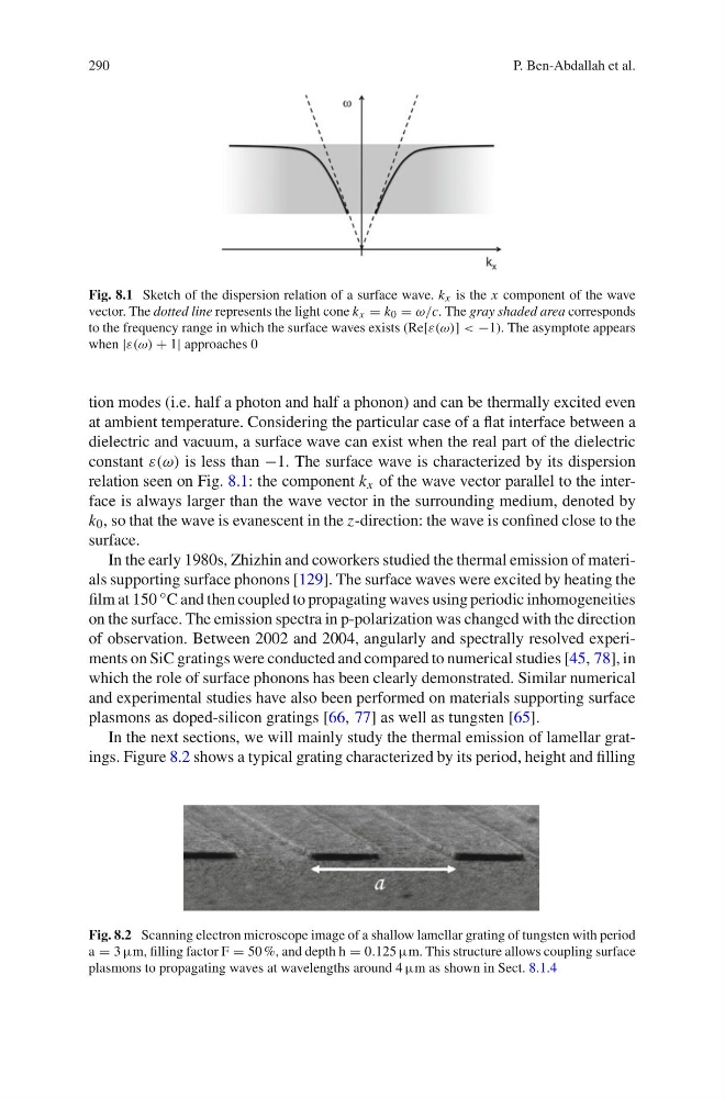
Fig. 8.1 Sketch of the dispersion relation of a surface wave. k x is the x component of the wave
vector. The dotted line represents the light cone k x = k 0 = ω/c. The gray shaded area corresponds
to the frequency range in which the surface waves exists (Re[ε(ω)] < −1). The asymptote appears
when |ε(ω) + 1| approaches 0
tion modes (i.e. half a photon and half a phonon) and can be thermally excited even
at ambient temperature. Considering the particular case of a flat interface between a
dielectric and vacuum, a surface wave can exist when the real part of the dielectric
constant ε(ω) is less than −1. The surface wave is characterized by its dispersion
relation seen on Fig. 8.1: the component k x of the wave vector parallel to the interface is always larger than the wave vector in the surrounding medium, denoted by
k 0 , so that the wave is evanescent in the z-direction: the wave is confined close to the
surface.
In the early 1980s, Zhizhin and coworkers studied the thermal emission of materials supporting surface phonons [129]. The surface waves were excited by heating the
film at 150 ◦ C and then coupled to propagating waves using periodic inhomogeneities
on the surface. The emission spectra in p-polarization was changed with the direction
of observation. Between 2002 and 2004, angularly and spectrally resolved experiments on SiC gratings were conducted and compared to numerical studies [45, 78], in
which the role of surface phonons has been clearly demonstrated. Similar numerical
and experimental studies have also been performed on materials supporting surface
plasmons as doped-silicon gratings [66, 77] as well as tungsten [65].
In the next sections, we will mainly study the thermal emission of lamellar gratings. Figure 8.2 shows a typical grating characterized by its period, height and filling
Fig. 8.2 Scanning electron microscope image of a shallow lamellar grating of tungsten with period
a = 3 µm, filling factor F = 50 %, and depth h = 0.125 µm. This structure allows coupling surface
plasmons to propagating waves at wavelengths around 4 µm as shown in Sect. 8.1.4
P. Ben-Abdallah et al.
Fig. 8.1 Sketch of the dispersion relation of a surface wave. k x is the x component of the wave
vector. The dotted line represents the light cone k x = k 0 = ω/c. The gray shaded area corresponds
to the frequency range in which the surface waves exists (Re[ε(ω)] < −1). The asymptote appears
when |ε(ω) + 1| approaches 0
tion modes (i.e. half a photon and half a phonon) and can be thermally excited even
at ambient temperature. Considering the particular case of a flat interface between a
dielectric and vacuum, a surface wave can exist when the real part of the dielectric
constant ε(ω) is less than −1. The surface wave is characterized by its dispersion
relation seen on Fig. 8.1: the component k x of the wave vector parallel to the interface is always larger than the wave vector in the surrounding medium, denoted by
k 0 , so that the wave is evanescent in the z-direction: the wave is confined close to the
surface.
In the early 1980s, Zhizhin and coworkers studied the thermal emission of materials supporting surface phonons [129]. The surface waves were excited by heating the
film at 150 ◦ C and then coupled to propagating waves using periodic inhomogeneities
on the surface. The emission spectra in p-polarization was changed with the direction
of observation. Between 2002 and 2004, angularly and spectrally resolved experiments on SiC gratings were conducted and compared to numerical studies [45, 78], in
which the role of surface phonons has been clearly demonstrated. Similar numerical
and experimental studies have also been performed on materials supporting surface
plasmons as doped-silicon gratings [66, 77] as well as tungsten [65].
In the next sections, we will mainly study the thermal emission of lamellar gratings. Figure 8.2 shows a typical grating characterized by its period, height and filling
Fig. 8.2 Scanning electron microscope image of a shallow lamellar grating of tungsten with period
a = 3 µm, filling factor F = 50 %, and depth h = 0.125 µm. This structure allows coupling surface
plasmons to propagating waves at wavelengths around 4 µm as shown in Sect. 8.1.4