

7 Ultrafast and Nonlinear Plasmon Dynamics
275
(a)
(b)
(d)
(c)
(e)
SPP
10 μm
0
3
-
0
2
-
0
1
-
0
0
1
0
2
0
3
Delay (fs)
SHG Wavelength (nm)
400
380
420
440
0 12 24
SHG Intensity (cps)
SHG Wavelength (nm)
430
410
450
390
SHG Intensity (cps)
0
12 24
0
6
-
0
4
-
0
2
-
0
0
2
0
4
0
6
0
8
Delay (fs)
750
800
850
900
0
0.25
0.5
0.75
1
Normalized Intensity
−π/2
π/2
0
Spec. Phase (rad)
750
800
850
900
0
0.25
0.5
0.75
1
0
Normalized Intensity
Wavelength (nm)
π
Spec. Phase (rad)
−π
20 nm
ω
2ω
Au tip
k in
k NF (ω,r)
-80
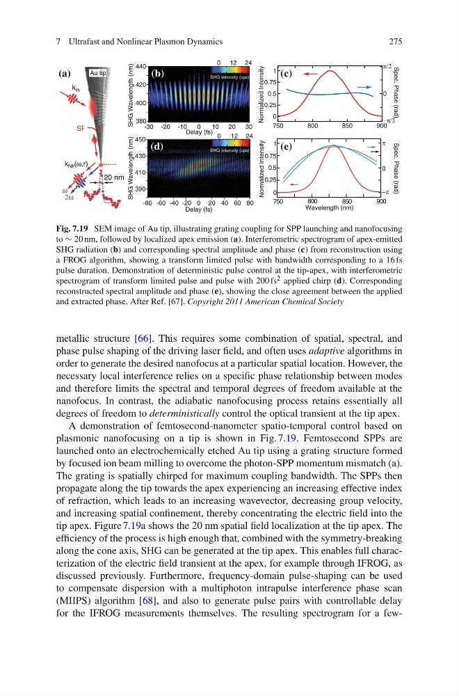
Fig. 7.19 SEM image of Au tip, illustrating grating coupling for SPP launching and nanofocusing
to ∝ 20 nm, followed by localized apex emission (a). Interferometric spectrogram of apex-emitted
SHG radiation (b) and corresponding spectral amplitude and phase (c) from reconstruction using
a FROG algorithm, showing a transform limited pulse with bandwidth corresponding to a 16 fs
pulse duration. Demonstration of deterministic pulse control at the tip-apex, with interferometric
spectrogram of transform limited pulse and pulse with 200 fs 2 applied chirp (d). Corresponding
reconstructed spectral amplitude and phase (e), showing the close agreement between the applied
and extracted phase. After Ref. [67]. Copyright 2011 American Chemical Society
metallic structure [66]. This requires some combination of spatial, spectral, and
phase pulse shaping of the driving laser field, and often uses adaptive algorithms in
order to generate the desired nanofocus at a particular spatial location. However, the
necessary local interference relies on a specific phase relationship between modes
and therefore limits the spectral and temporal degrees of freedom available at the
nanofocus. In contrast, the adiabatic nanofocusing process retains essentially all
degrees of freedom to deterministically control the optical transient at the tip apex.
A demonstration of femtosecond-nanometer spatio-temporal control based on
plasmonic nanofocusing on a tip is shown in Fig. 7.19. Femtosecond SPPs are
launched onto an electrochemically etched Au tip using a grating structure formed
by focused ion beam milling to overcome the photon-SPP momentum mismatch (a).
The grating is spatially chirped for maximum coupling bandwidth. The SPPs then
propagate along the tip towards the apex experiencing an increasing effective index
of refraction, which leads to an increasing wavevector, decreasing group velocity,
and increasing spatial confinement, thereby concentrating the electric field into the
tip apex. Figure 7.19a shows the 20 nm spatial field localization at the tip apex. The
efficiency of the process is high enough that, combined with the symmetry-breaking
along the cone axis, SHG can be generated at the tip apex. This enables full characterization of the electric field transient at the apex, for example through IFROG, as
discussed previously. Furthermore, frequency-domain pulse-shaping can be used
to compensate dispersion with a multiphoton intrapulse interference phase scan
(MIIPS) algorithm [68], and also to generate pulse pairs with controllable delay
for the IFROG measurements themselves. The resulting spectrogram for a few-
275
(a)
(b)
(d)
(c)
(e)
SPP
10 μm
0
3
-
0
2
-
0
1
-
0
0
1
0
2
0
3
Delay (fs)
SHG Wavelength (nm)
400
380
420
440
0 12 24
SHG Intensity (cps)
SHG Wavelength (nm)
430
410
450
390
SHG Intensity (cps)
0
12 24
0
6
-
0
4
-
0
2
-
0
0
2
0
4
0
6
0
8
Delay (fs)
750
800
850
900
0
0.25
0.5
0.75
1
Normalized Intensity
−π/2
π/2
0
Spec. Phase (rad)
750
800
850
900
0
0.25
0.5
0.75
1
0
Normalized Intensity
Wavelength (nm)
π
Spec. Phase (rad)
−π
20 nm
ω
2ω
Au tip
k in
k NF (ω,r)
-80
Fig. 7.19 SEM image of Au tip, illustrating grating coupling for SPP launching and nanofocusing
to ∝ 20 nm, followed by localized apex emission (a). Interferometric spectrogram of apex-emitted
SHG radiation (b) and corresponding spectral amplitude and phase (c) from reconstruction using
a FROG algorithm, showing a transform limited pulse with bandwidth corresponding to a 16 fs
pulse duration. Demonstration of deterministic pulse control at the tip-apex, with interferometric
spectrogram of transform limited pulse and pulse with 200 fs 2 applied chirp (d). Corresponding
reconstructed spectral amplitude and phase (e), showing the close agreement between the applied
and extracted phase. After Ref. [67]. Copyright 2011 American Chemical Society
metallic structure [66]. This requires some combination of spatial, spectral, and
phase pulse shaping of the driving laser field, and often uses adaptive algorithms in
order to generate the desired nanofocus at a particular spatial location. However, the
necessary local interference relies on a specific phase relationship between modes
and therefore limits the spectral and temporal degrees of freedom available at the
nanofocus. In contrast, the adiabatic nanofocusing process retains essentially all
degrees of freedom to deterministically control the optical transient at the tip apex.
A demonstration of femtosecond-nanometer spatio-temporal control based on
plasmonic nanofocusing on a tip is shown in Fig. 7.19. Femtosecond SPPs are
launched onto an electrochemically etched Au tip using a grating structure formed
by focused ion beam milling to overcome the photon-SPP momentum mismatch (a).
The grating is spatially chirped for maximum coupling bandwidth. The SPPs then
propagate along the tip towards the apex experiencing an increasing effective index
of refraction, which leads to an increasing wavevector, decreasing group velocity,
and increasing spatial confinement, thereby concentrating the electric field into the
tip apex. Figure 7.19a shows the 20 nm spatial field localization at the tip apex. The
efficiency of the process is high enough that, combined with the symmetry-breaking
along the cone axis, SHG can be generated at the tip apex. This enables full characterization of the electric field transient at the apex, for example through IFROG, as
discussed previously. Furthermore, frequency-domain pulse-shaping can be used
to compensate dispersion with a multiphoton intrapulse interference phase scan
(MIIPS) algorithm [68], and also to generate pulse pairs with controllable delay
for the IFROG measurements themselves. The resulting spectrogram for a few-