

6 Second-Order Nonlinear Optical Properties of Plasmonic Nanostructures
213
6.3.2 Experimental Setup
The linear optical properties of the samples were determined by measuring their
extinction spectra. These measurements were performed at normal incidence using
a fiber-coupled halogen lamp as a light source. Microscope objectives were used
to collimate light from the fiber and to focus the light into the pick-up fiber of the
spectrometer. A calcite polarizer was used to set linear polarization state and a pinhole
was placed in order to illuminate the desired sample area. Two spectrometers were
used to cover a spectral range from 400 to 1700 nm.
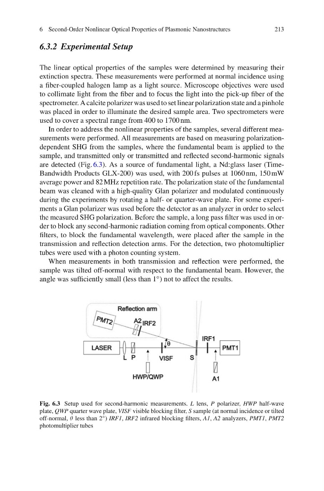
In order to address the nonlinear properties of the samples, several different measurements were performed. All measurements are based on measuring polarizationdependent SHG from the samples, where the fundamental beam is applied to the
sample, and transmitted only or transmitted and reflected second-harmonic signals
are detected (Fig. 6.3). As a source of fundamental light, a Nd:glass laser (TimeBandwidth Products GLX-200) was used, with 200 fs pulses at 1060 nm, 150 mW
average power and 82 MHz repetition rate. The polarization state of the fundamental
beam was cleaned with a high-quality Glan polarizer and modulated continuously
during the experiments by rotating a half- or quarter-wave plate. For some experiments a Glan polarizer was used before the detector as an analyzer in order to select
the measured SHG polarization. Before the sample, a long pass filter was used in order to block any second-harmonic radiation coming from optical components. Other
filters, to block the fundamental wavelength, were placed after the sample in the
transmission and reflection detection arms. For the detection, two photomultiplier
tubes were used with a photon counting system.
When measurements in both transmission and reflection were performed, the
sample was tilted off-normal with respect to the fundamental beam. However, the
angle was sufficiently small (less than 1 ◦ ) not to affect the results.
Fig. 6.3 Setup used for second-harmonic measurements. L lens, P polarizer, HWP half-wave
plate, QWP quarter wave plate, VISF visible blocking filter, S sample (at normal incidence or tilted
off-normal, θ less than 2 ◦ ) IRF1, IRF2 infrared blocking filters, A1, A2 analyzers, PMT1, PMT2
photomultiplier tubes
213
6.3.2 Experimental Setup
The linear optical properties of the samples were determined by measuring their
extinction spectra. These measurements were performed at normal incidence using
a fiber-coupled halogen lamp as a light source. Microscope objectives were used
to collimate light from the fiber and to focus the light into the pick-up fiber of the
spectrometer. A calcite polarizer was used to set linear polarization state and a pinhole
was placed in order to illuminate the desired sample area. Two spectrometers were
used to cover a spectral range from 400 to 1700 nm.
In order to address the nonlinear properties of the samples, several different measurements were performed. All measurements are based on measuring polarizationdependent SHG from the samples, where the fundamental beam is applied to the
sample, and transmitted only or transmitted and reflected second-harmonic signals
are detected (Fig. 6.3). As a source of fundamental light, a Nd:glass laser (TimeBandwidth Products GLX-200) was used, with 200 fs pulses at 1060 nm, 150 mW
average power and 82 MHz repetition rate. The polarization state of the fundamental
beam was cleaned with a high-quality Glan polarizer and modulated continuously
during the experiments by rotating a half- or quarter-wave plate. For some experiments a Glan polarizer was used before the detector as an analyzer in order to select
the measured SHG polarization. Before the sample, a long pass filter was used in order to block any second-harmonic radiation coming from optical components. Other
filters, to block the fundamental wavelength, were placed after the sample in the
transmission and reflection detection arms. For the detection, two photomultiplier
tubes were used with a photon counting system.
When measurements in both transmission and reflection were performed, the
sample was tilted off-normal with respect to the fundamental beam. However, the
angle was sufficiently small (less than 1 ◦ ) not to affect the results.
Fig. 6.3 Setup used for second-harmonic measurements. L lens, P polarizer, HWP half-wave
plate, QWP quarter wave plate, VISF visible blocking filter, S sample (at normal incidence or tilted
off-normal, θ less than 2 ◦ ) IRF1, IRF2 infrared blocking filters, A1, A2 analyzers, PMT1, PMT2
photomultiplier tubes