

44
K. D. Dahm and D. J. Dahm
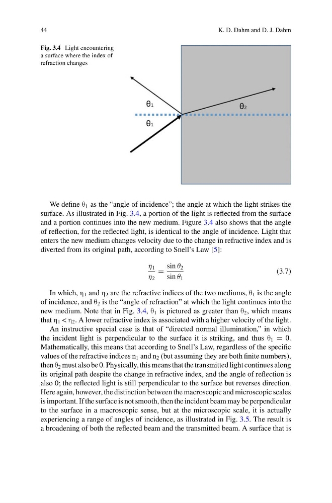
Fig. 3.4 Light encountering
a surface where the index of
refraction changes
We define θ 1 as the “angle of incidence”; the angle at which the light strikes the
surface. As illustrated in Fig. 3.4, a portion of the light is reflected from the surface
and a portion continues into the new medium. Figure 3.4 also shows that the angle
of reflection, for the reflected light, is identical to the angle of incidence. Light that
enters the new medium changes velocity due to the change in refractive index and is
diverted from its original path, according to Snell’s Law [5]:
η 1
η 2
=
sin θ 2
sin θ 1
(3.7)
In which, η 1 and η 2 are the refractive indices of the two mediums, θ 1 is the angle
of incidence, and θ 2 is the “angle of refraction” at which the light continues into the
new medium. Note that in Fig. 3.4, θ 1 is pictured as greater than θ 2 , which means
that η 1 < η 2 . A lower refractive index is associated with a higher velocity of the light.
An instructive special case is that of “directed normal illumination,” in which
the incident light is perpendicular to the surface it is striking, and thus θ 1 = 0.
Mathematically, this means that according to Snell’s Law, regardless of the specific
values of the refractive indices n 1 and n 2 (but assuming they are both finite numbers),
then θ 2 must also be 0. Physically, this means that the transmitted light continues along
its original path despite the change in refractive index, and the angle of reflection is
also 0; the reflected light is still perpendicular to the surface but reverses direction.
Here again, however, the distinction between the macroscopic and microscopic scales
is important. If the surface is not smooth, then the incident beam may be perpendicular
to the surface in a macroscopic sense, but at the microscopic scale, it is actually
experiencing a range of angles of incidence, as illustrated in Fig. 3.5. The result is
a broadening of both the reflected beam and the transmitted beam. A surface that is
K. D. Dahm and D. J. Dahm
Fig. 3.4 Light encountering
a surface where the index of
refraction changes
We define θ 1 as the “angle of incidence”; the angle at which the light strikes the
surface. As illustrated in Fig. 3.4, a portion of the light is reflected from the surface
and a portion continues into the new medium. Figure 3.4 also shows that the angle
of reflection, for the reflected light, is identical to the angle of incidence. Light that
enters the new medium changes velocity due to the change in refractive index and is
diverted from its original path, according to Snell’s Law [5]:
η 1
η 2
=
sin θ 2
sin θ 1
(3.7)
In which, η 1 and η 2 are the refractive indices of the two mediums, θ 1 is the angle
of incidence, and θ 2 is the “angle of refraction” at which the light continues into the
new medium. Note that in Fig. 3.4, θ 1 is pictured as greater than θ 2 , which means
that η 1 < η 2 . A lower refractive index is associated with a higher velocity of the light.
An instructive special case is that of “directed normal illumination,” in which
the incident light is perpendicular to the surface it is striking, and thus θ 1 = 0.
Mathematically, this means that according to Snell’s Law, regardless of the specific
values of the refractive indices n 1 and n 2 (but assuming they are both finite numbers),
then θ 2 must also be 0. Physically, this means that the transmitted light continues along
its original path despite the change in refractive index, and the angle of reflection is
also 0; the reflected light is still perpendicular to the surface but reverses direction.
Here again, however, the distinction between the macroscopic and microscopic scales
is important. If the surface is not smooth, then the incident beam may be perpendicular
to the surface in a macroscopic sense, but at the microscopic scale, it is actually
experiencing a range of angles of incidence, as illustrated in Fig. 3.5. The result is
a broadening of both the reflected beam and the transmitted beam. A surface that is