

246
T. Okura
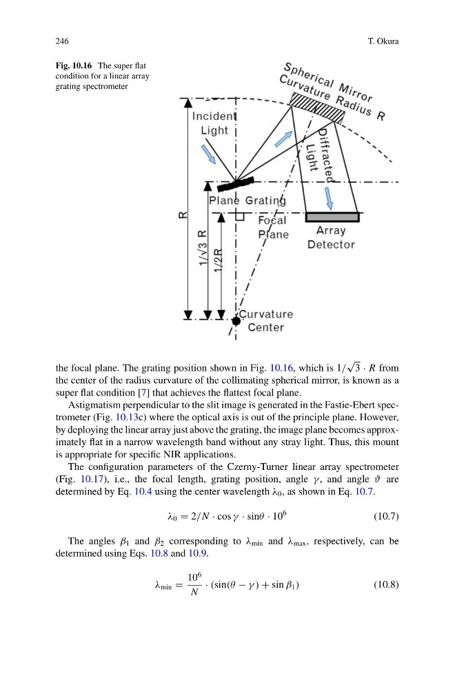
Fig. 10.16 The super flat
condition for a linear array
grating spectrometer
the focal plane. The grating position shown in Fig. 10.16, which is 1/
√
3 · R from
the center of the radius curvature of the collimating spherical mirror, is known as a
super flat condition [7] that achieves the flattest focal plane.
Astigmatism perpendicular to the slit image is generated in the Fastie-Ebert spectrometer (Fig. 10.13c) where the optical axis is out of the principle plane. However,
by deploying the linear array just above the grating, the image plane becomes approximately flat in a narrow wavelength band without any stray light. Thus, this mount
is appropriate for specific NIR applications.
The configuration parameters of the Czerny-Turner linear array spectrometer
(Fig. 10.17), i.e., the focal length, grating position, angle γ , and angle ϑ are
determined by Eq. 10.4 using the center wavelength λ 0 , as shown in Eq. 10.7.
λ 0 = 2/N · cos γ · sinθ · 10
6
(10.7)
The angles β 1 and β 2 corresponding to λ min and λ max , respectively, can be
determined using Eqs. 10.8 and 10.9.
λ min =
10
6
N
· (sin(θ − γ ) + sin β 1 )
(10.8)
T. Okura
Fig. 10.16 The super flat
condition for a linear array
grating spectrometer
the focal plane. The grating position shown in Fig. 10.16, which is 1/
√
3 · R from
the center of the radius curvature of the collimating spherical mirror, is known as a
super flat condition [7] that achieves the flattest focal plane.
Astigmatism perpendicular to the slit image is generated in the Fastie-Ebert spectrometer (Fig. 10.13c) where the optical axis is out of the principle plane. However,
by deploying the linear array just above the grating, the image plane becomes approximately flat in a narrow wavelength band without any stray light. Thus, this mount
is appropriate for specific NIR applications.
The configuration parameters of the Czerny-Turner linear array spectrometer
(Fig. 10.17), i.e., the focal length, grating position, angle γ , and angle ϑ are
determined by Eq. 10.4 using the center wavelength λ 0 , as shown in Eq. 10.7.
λ 0 = 2/N · cos γ · sinθ · 10
6
(10.7)
The angles β 1 and β 2 corresponding to λ min and λ max , respectively, can be
determined using Eqs. 10.8 and 10.9.
λ min =
10
6
N
· (sin(θ − γ ) + sin β 1 )
(10.8)