

5.3 Laser Specklometer (Microhematomyograph) …
385
To obtain the maximal contrast of the exit signal, the final size of a speckle in the
plane of the input window of the receiving light guide should be ≈5 μm that is why
the receiving light guide has to be put at a distance S 2 from the surface under study,
which we determine from the expression
S 2 =
Dd
1.22λ
=
1.4 · 5 · 10
−3
1.22 · 0.633 · 10 −3 ≈ 9 mm
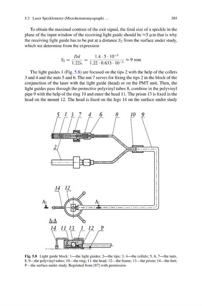
The light guides 1 (Fig. 5.8) are focused on the tips 2 with the help of the collets
3 and 4 and the nuts 5 and 6. The nut 7 serves for fixing the tips 2 in the block of the
conjunction of the laser with the light guide (head) or on the PMT unit. Then, the
light guides pass through the protective polyvinyl tubes 8, combine in the polyvinyl
pipe 9 with the help of the ring 10 and enter the head 11. The prism 13 is fixed in the
head on the mount 12. The head is fixed on the legs 14 on the surface under study
Fig. 5.8 Light guide block: 1—the light guides; 2—the tips; 3, 4—the collets; 5, 6, 7—the nuts,
8, 9—the polyvinyl tubes; 10—the ring; 11–the head; 12—the frame; 13—the prism; 14—the feet;
P—the surface under study. Reprinted from [87] with permission
385
To obtain the maximal contrast of the exit signal, the final size of a speckle in the
plane of the input window of the receiving light guide should be ≈5 μm that is why
the receiving light guide has to be put at a distance S 2 from the surface under study,
which we determine from the expression
S 2 =
Dd
1.22λ
=
1.4 · 5 · 10
−3
1.22 · 0.633 · 10 −3 ≈ 9 mm
The light guides 1 (Fig. 5.8) are focused on the tips 2 with the help of the collets
3 and 4 and the nuts 5 and 6. The nut 7 serves for fixing the tips 2 in the block of the
conjunction of the laser with the light guide (head) or on the PMT unit. Then, the
light guides pass through the protective polyvinyl tubes 8, combine in the polyvinyl
pipe 9 with the help of the ring 10 and enter the head 11. The prism 13 is fixed in the
head on the mount 12. The head is fixed on the legs 14 on the surface under study
Fig. 5.8 Light guide block: 1—the light guides; 2—the tips; 3, 4—the collets; 5, 6, 7—the nuts,
8, 9—the polyvinyl tubes; 10—the ring; 11–the head; 12—the frame; 13—the prism; 14—the feet;
P—the surface under study. Reprinted from [87] with permission