

384
5 Laser Specklometer, Speckle-Optical Diagnostics and Laser …
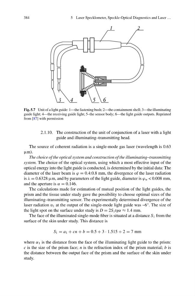
Fig. 5.7 Unit of a light guide: 1—the fastening bush; 2—the containment shell; 3—the illuminating
guide light; 4—the receiving guide light; 5–the sensor body; 6—the light guide outputs. Reprinted
from [87] with permission
2.1.10. The construction of the unit of conjunction of a laser with a light
guide and illuminating–transmitting head.
The source of coherent radiation is a single-mode gas laser (wavelength is 0.63
μm).
The choice of the optical system and construction of the illuminating–transmitting
system. The choice of the optical system, using which a most effective input of the
optical energy into the light guide is conducted, is determined by the initial data: The
diameter of the laser beam is ϕ = 0.4:0.8 mm, the divergence of the laser radiation
is λ = 0.6328 μm, and by parameters of the light guide, diameter is ϕ w < 0.008 mm,
and the aperture is α = 0.146.
The calculations made for estimation of mutual position of the light guides, the
prism and the tissue under study gave the possibility to choose optimal sizes of the
illuminating–transmitting sensor. The experimentally determined divergence of the
laser radiation α 1 at the output of the single-mode light guide was ~6°. The size of
the light spot on the surface under study is D = 2S 1 tgα ≈ 1.4 mm.
The face of the illuminated single-mode fiber is situated at a distance S 1 from the
surface of the skin under study. This distance is
S 1 = a 1 + cn + b = 0.5 + 3 · 1.515 + 2 = 7 mm
where α 1 is the distance from the face of the illuminating light guide to the prism:
c is the size of the prism face; n is the refraction index of the prism material; b is
the distance between the output face of the prism and the surface of the skin under
study.
5 Laser Specklometer, Speckle-Optical Diagnostics and Laser …
Fig. 5.7 Unit of a light guide: 1—the fastening bush; 2—the containment shell; 3—the illuminating
guide light; 4—the receiving guide light; 5–the sensor body; 6—the light guide outputs. Reprinted
from [87] with permission
2.1.10. The construction of the unit of conjunction of a laser with a light
guide and illuminating–transmitting head.
The source of coherent radiation is a single-mode gas laser (wavelength is 0.63
μm).
The choice of the optical system and construction of the illuminating–transmitting
system. The choice of the optical system, using which a most effective input of the
optical energy into the light guide is conducted, is determined by the initial data: The
diameter of the laser beam is ϕ = 0.4:0.8 mm, the divergence of the laser radiation
is λ = 0.6328 μm, and by parameters of the light guide, diameter is ϕ w < 0.008 mm,
and the aperture is α = 0.146.
The calculations made for estimation of mutual position of the light guides, the
prism and the tissue under study gave the possibility to choose optimal sizes of the
illuminating–transmitting sensor. The experimentally determined divergence of the
laser radiation α 1 at the output of the single-mode light guide was ~6°. The size of
the light spot on the surface under study is D = 2S 1 tgα ≈ 1.4 mm.
The face of the illuminated single-mode fiber is situated at a distance S 1 from the
surface of the skin under study. This distance is
S 1 = a 1 + cn + b = 0.5 + 3 · 1.515 + 2 = 7 mm
where α 1 is the distance from the face of the illuminating light guide to the prism:
c is the size of the prism face; n is the refraction index of the prism material; b is
the distance between the output face of the prism and the surface of the skin under
study.