

14
1 Resonance Methods for Increasing Sensitivity of Interferometry …
|γ 12 | =
2J 1
πν 0 dpy
f ( p−y)
πν 0 dpy
f ( p−y)
,
(1.20)
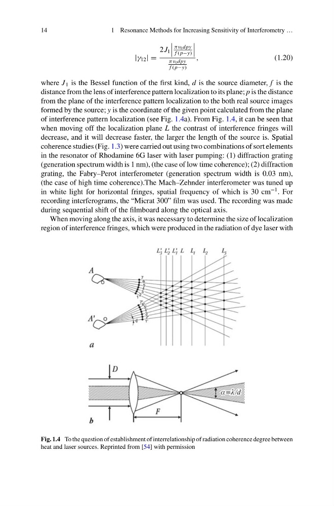
where J 1 is the Bessel function of the first kind, d is the source diameter, f is the
distance from the lens of interference pattern localization to its plane; p is the distance
from the plane of the interference pattern localization to the both real source images
formed by the source; y is the coordinate of the given point calculated from the plane
of interference pattern localization (see Fig. 1.4a). From Fig. 1.4, it can be seen that
when moving off the localization plane L the contrast of interference fringes will
decrease, and it will decrease faster, the larger the length of the source is. Spatial
coherence studies (Fig. 1.3) were carried out using two combinations of sort elements
in the resonator of Rhodamine 6G laser with laser pumping: (1) diffraction grating
(generation spectrum width is 1 nm), (the case of low time coherence); (2) diffraction
grating, the Fabry–Perot interferometer (generation spectrum width is 0.03 nm),
(the case of high time coherence).The Mach–Zehnder interferometer was tuned up
in white light for horizontal fringes, spatial frequency of which is 30 cm
−1 . For
recording interferograms, the “Micrat 300” film was used. The recording was made
during sequential shift of the filmboard along the optical axis.
When moving along the axis, it was necessary to determine the size of localization
region of interference fringes, which were produced in the radiation of dye laser with
Fig. 1.4 To the question of establishment of interrelationship of radiation coherence degree between
heat and laser sources. Reprinted from [54] with permission
1 Resonance Methods for Increasing Sensitivity of Interferometry …
|γ 12 | =
2J 1
πν 0 dpy
f ( p−y)
πν 0 dpy
f ( p−y)
,
(1.20)
where J 1 is the Bessel function of the first kind, d is the source diameter, f is the
distance from the lens of interference pattern localization to its plane; p is the distance
from the plane of the interference pattern localization to the both real source images
formed by the source; y is the coordinate of the given point calculated from the plane
of interference pattern localization (see Fig. 1.4a). From Fig. 1.4, it can be seen that
when moving off the localization plane L the contrast of interference fringes will
decrease, and it will decrease faster, the larger the length of the source is. Spatial
coherence studies (Fig. 1.3) were carried out using two combinations of sort elements
in the resonator of Rhodamine 6G laser with laser pumping: (1) diffraction grating
(generation spectrum width is 1 nm), (the case of low time coherence); (2) diffraction
grating, the Fabry–Perot interferometer (generation spectrum width is 0.03 nm),
(the case of high time coherence).The Mach–Zehnder interferometer was tuned up
in white light for horizontal fringes, spatial frequency of which is 30 cm
−1 . For
recording interferograms, the “Micrat 300” film was used. The recording was made
during sequential shift of the filmboard along the optical axis.
When moving along the axis, it was necessary to determine the size of localization
region of interference fringes, which were produced in the radiation of dye laser with
Fig. 1.4 To the question of establishment of interrelationship of radiation coherence degree between
heat and laser sources. Reprinted from [54] with permission