

382
5 Laser Specklometer, Speckle-Optical Diagnostics and Laser …
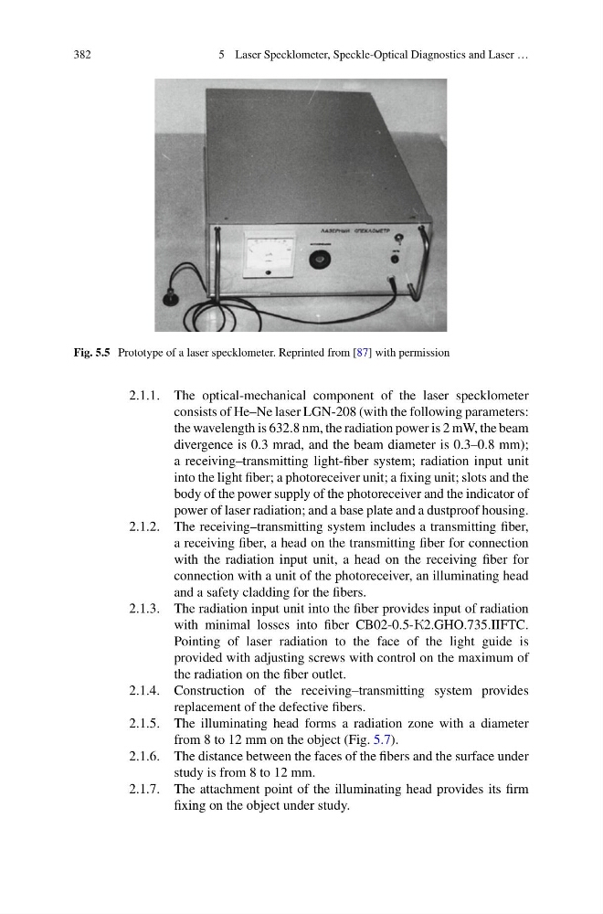
Fig. 5.5 Prototype of a laser specklometer. Reprinted from [87] with permission
2.1.1. The optical-mechanical component of the laser specklometer
consists of He–Ne laser LGN-208 (with the following parameters:
the wavelength is 632.8 nm, the radiation power is 2 mW, the beam
divergence is 0.3 mrad, and the beam diameter is 0.3–0.8 mm);
a receiving–transmitting light-fiber system; radiation input unit
into the light fiber; a photoreceiver unit; a fixing unit; slots and the
body of the power supply of the photoreceiver and the indicator of
power of laser radiation; and a base plate and a dustproof housing.
2.1.2. The receiving–transmitting system includes a transmitting fiber,
a receiving fiber, a head on the transmitting fiber for connection
with the radiation input unit, a head on the receiving fiber for
connection with a unit of the photoreceiver, an illuminating head
and a safety cladding for the fibers.
2.1.3. The radiation input unit into the fiber provides input of radiation
with minimal losses into fiber CB02-0.5-K2.GHO.735.IIFTC.
Pointing of laser radiation to the face of the light guide is
provided with adjusting screws with control on the maximum of
the radiation on the fiber outlet.
2.1.4. Construction of the receiving–transmitting system provides
replacement of the defective fibers.
2.1.5. The illuminating head forms a radiation zone with a diameter
from 8 to 12 mm on the object (Fig. 5.7).
2.1.6. The distance between the faces of the fibers and the surface under
study is from 8 to 12 mm.
2.1.7. The attachment point of the illuminating head provides its firm
fixing on the object under study.
5 Laser Specklometer, Speckle-Optical Diagnostics and Laser …
Fig. 5.5 Prototype of a laser specklometer. Reprinted from [87] with permission
2.1.1. The optical-mechanical component of the laser specklometer
consists of He–Ne laser LGN-208 (with the following parameters:
the wavelength is 632.8 nm, the radiation power is 2 mW, the beam
divergence is 0.3 mrad, and the beam diameter is 0.3–0.8 mm);
a receiving–transmitting light-fiber system; radiation input unit
into the light fiber; a photoreceiver unit; a fixing unit; slots and the
body of the power supply of the photoreceiver and the indicator of
power of laser radiation; and a base plate and a dustproof housing.
2.1.2. The receiving–transmitting system includes a transmitting fiber,
a receiving fiber, a head on the transmitting fiber for connection
with the radiation input unit, a head on the receiving fiber for
connection with a unit of the photoreceiver, an illuminating head
and a safety cladding for the fibers.
2.1.3. The radiation input unit into the fiber provides input of radiation
with minimal losses into fiber CB02-0.5-K2.GHO.735.IIFTC.
Pointing of laser radiation to the face of the light guide is
provided with adjusting screws with control on the maximum of
the radiation on the fiber outlet.
2.1.4. Construction of the receiving–transmitting system provides
replacement of the defective fibers.
2.1.5. The illuminating head forms a radiation zone with a diameter
from 8 to 12 mm on the object (Fig. 5.7).
2.1.6. The distance between the faces of the fibers and the surface under
study is from 8 to 12 mm.
2.1.7. The attachment point of the illuminating head provides its firm
fixing on the object under study.