

376
5 Laser Specklometer, Speckle-Optical Diagnostics and Laser …
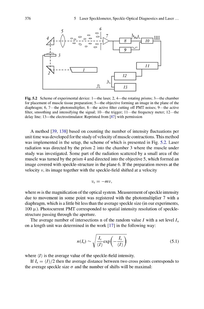
Fig. 5.2 Scheme of experimental device: 1—the laser, 2, 4—the rotating prisms; 3—the chamber
for placement of muscle tissue preparation; 5—the objective forming an image in the plane of the
diaphragm; 6, 7—the photomultiplier, 8—the active filter cutting off PMT noises; 9—the active
filter, smoothing and intensifying the signal; 10—the trigger; 11—the frequency meter; 12—the
delay line; 13—the electrostimulator. Reprinted from [87] with permission
A method [39, 138] based on counting the number of intensity fluctuations per
unit time was developed for the study of velocity of muscle contractions. This method
was implemented in the setup, the scheme of which is presented in Fig. 5.2. Laser
radiation was directed by the prism 2 into the chamber 3 where the muscle under
study was investigated. Some part of the radiation scattered by a small area of the
muscle was turned by the prism 4 and directed into the objective 5, which formed an
image covered with speckle-structure in the plane 6. If the preparation moves at the
velocity ν, its image together with the speckle-field shifted at a velocity
ν s = −mν,
where m is the magnification of the optical system. Measurement of speckle intensity
due to movement in some point was registered with the photomultiplier 7 with a
diaphragm, which is a little bit less than the average speckle size (in our experiments,
100 μ). Photocurrent PMT corresponded to spatial intensity resolution of specklestructure passing through the aperture.
The average number of intersections n of the random value I with a set level I s
on a length unit was determined in the work [17] in the following way:
n(I s ) ∼
I s
I
exp
−
I s
I
(5.1)
where I is the average value of the speckle-field intensity.
If I s = =I /2 then the average distance between two cross points corresponds to
the average speckle size σ and the number of shifts will be maximal:
5 Laser Specklometer, Speckle-Optical Diagnostics and Laser …
Fig. 5.2 Scheme of experimental device: 1—the laser, 2, 4—the rotating prisms; 3—the chamber
for placement of muscle tissue preparation; 5—the objective forming an image in the plane of the
diaphragm; 6, 7—the photomultiplier, 8—the active filter cutting off PMT noises; 9—the active
filter, smoothing and intensifying the signal; 10—the trigger; 11—the frequency meter; 12—the
delay line; 13—the electrostimulator. Reprinted from [87] with permission
A method [39, 138] based on counting the number of intensity fluctuations per
unit time was developed for the study of velocity of muscle contractions. This method
was implemented in the setup, the scheme of which is presented in Fig. 5.2. Laser
radiation was directed by the prism 2 into the chamber 3 where the muscle under
study was investigated. Some part of the radiation scattered by a small area of the
muscle was turned by the prism 4 and directed into the objective 5, which formed an
image covered with speckle-structure in the plane 6. If the preparation moves at the
velocity ν, its image together with the speckle-field shifted at a velocity
ν s = −mν,
where m is the magnification of the optical system. Measurement of speckle intensity
due to movement in some point was registered with the photomultiplier 7 with a
diaphragm, which is a little bit less than the average speckle size (in our experiments,
100 μ). Photocurrent PMT corresponded to spatial intensity resolution of specklestructure passing through the aperture.
The average number of intersections n of the random value I with a set level I s
on a length unit was determined in the work [17] in the following way:
n(I s ) ∼
I s
I
exp
−
I s
I
(5.1)
where I is the average value of the speckle-field intensity.
If I s = =I /2 then the average distance between two cross points corresponds to
the average speckle size σ and the number of shifts will be maximal: