

4.8 Method for Measurement of Movement Velocity Vector of Diffuse Objects
353
All the results are reliable at significance level p = 0.05. It is seen from the
comparison of υ 1 and υ 2 that velocity is codirectional with δν in the first case,
which was actually realized in the experiment. Average values = (υ 1 + υ 2 )/2, which
describe velocity module || υ|, lie well onto a straight line.
Thus, as a result of this study, a non-contact method of speckle-optics for determination of two-dimensional travel velocity vector of the diffuse object was suggested
and developed, which is based on additional modulation of speckle-fields. An electronic device was created for the calculation of the number of speckles passing
through PMT aperture per unit of time and for measurement of velocity module. The
experimental check of this method on models provided a measurement of velocities
in the range of 3–50 cm/s with an error of about 5%.
4.9 About Formation of Annular Speckle-Interferograms
Emerging During Longitudinal Shift
It is known that double-exposure speckle-photography is mainly used for measurement of transverse shifts, and it has the greatest sensitivity to such shifts [44, 48].
Fourier transformation of the negative, on which there was registered image of the
object covered with speckles, in initial and shifted states gives the opportunity to
obtain equidistant interference fringes, which are known as Yung’s fringes, according
to which the required transversal shift is easily calculated. Along with this, specklephotography allows determining the longitudinal shift of the diffuse object as well
[58]. But speckle-interferograms themselves as well as their forming conditions
considerably differ in both cases.
This work considers the process of formation of interference fringes corresponding to a longitudinal shift of the objective. Let two speckle-fields with intensity distribution I 1 ( x) and I 2 ( x) be linearly registered on photomaterial S p , and its
transmittance be described with expression
t = t 0 − t 1
I 1 ( x) − I 2 ( x)
(4.81)
where t 0 and t 1 are the constants;
x is the two-dimensional vector in plane S p .
We illuminate such a specklogram with a plane wave u 0 and behind it at distance
d we place the optical system O b with pulse response K( x,
X, d, p) where
X is the
coordinate in the observation plane P; p is the distance between the objective and P
(Fig. 4.22). Part of the light t 0 u 0 passed the specklogram without diffraction can be
filtered by placing the minor blocking screen.
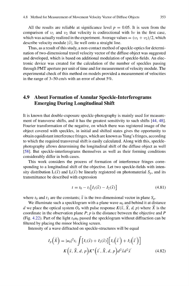
Intensity of a wave diffracted on speckle-structures will be equal
I p
X
= |u 0 |
2 t 1
I 1 ( x) + I 2 ( x)
I 1
x
+ I 2
x
K
x,
X , d, p
K
∗
x
,
X , d, p
d
2
xd
2
x
(4.82)
353
All the results are reliable at significance level p = 0.05. It is seen from the
comparison of υ 1 and υ 2 that velocity is codirectional with δν in the first case,
which was actually realized in the experiment. Average values = (υ 1 + υ 2 )/2, which
describe velocity module || υ|, lie well onto a straight line.
Thus, as a result of this study, a non-contact method of speckle-optics for determination of two-dimensional travel velocity vector of the diffuse object was suggested
and developed, which is based on additional modulation of speckle-fields. An electronic device was created for the calculation of the number of speckles passing
through PMT aperture per unit of time and for measurement of velocity module. The
experimental check of this method on models provided a measurement of velocities
in the range of 3–50 cm/s with an error of about 5%.
4.9 About Formation of Annular Speckle-Interferograms
Emerging During Longitudinal Shift
It is known that double-exposure speckle-photography is mainly used for measurement of transverse shifts, and it has the greatest sensitivity to such shifts [44, 48].
Fourier transformation of the negative, on which there was registered image of the
object covered with speckles, in initial and shifted states gives the opportunity to
obtain equidistant interference fringes, which are known as Yung’s fringes, according
to which the required transversal shift is easily calculated. Along with this, specklephotography allows determining the longitudinal shift of the diffuse object as well
[58]. But speckle-interferograms themselves as well as their forming conditions
considerably differ in both cases.
This work considers the process of formation of interference fringes corresponding to a longitudinal shift of the objective. Let two speckle-fields with intensity distribution I 1 ( x) and I 2 ( x) be linearly registered on photomaterial S p , and its
transmittance be described with expression
t = t 0 − t 1
I 1 ( x) − I 2 ( x)
(4.81)
where t 0 and t 1 are the constants;
x is the two-dimensional vector in plane S p .
We illuminate such a specklogram with a plane wave u 0 and behind it at distance
d we place the optical system O b with pulse response K( x,
X, d, p) where
X is the
coordinate in the observation plane P; p is the distance between the objective and P
(Fig. 4.22). Part of the light t 0 u 0 passed the specklogram without diffraction can be
filtered by placing the minor blocking screen.
Intensity of a wave diffracted on speckle-structures will be equal
I p
X
= |u 0 |
2 t 1
I 1 ( x) + I 2 ( x)
I 1
x
+ I 2
x
K
x,
X , d, p
K
∗
x
,
X , d, p
d
2
xd
2
x
(4.82)