

352
4 Speckle-Optical Methods and Devices for Studying …
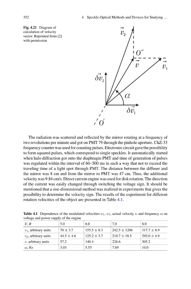
Fig. 4.21 Diagram of
calculation of velocity
vector. Reprinted from [2]
with permission
The radiation was scattered and reflected by the mirror rotating at a frequency of
two revolutions per minute and got on PMT 79 through the pinhole aperture. ChZ-33
frequency counter was used for counting pulses. Electronic circuit gave the possibility
to form squared pulses, which correspond to single speckles. It automatically started
when halo diffraction got onto the diaphragm PMT and time of generation of pulses
was regulated within the interval of 60–500 ms in such a way that not to exceed the
traveling time of a light spot through PMT. The distance between the diffuser and
the mirror was 8 cm and from the mirror to PMT was 47 cm. Thus, the additional
velocity was 9.84 cm/s. Direct current engine was used for disk rotation. The direction
of the current was easily changed through switching the voltage sign. It should be
mentioned that a one-dimensional method was realized in experiments that gives the
possibility to determine the velocity sign. The results of the experiment for different
rotation velocities of the object are presented in Table 4.1.
Table 4.1 Dependence of the modulated velocities υ 1 , υ 2 , actual velocity υ and frequency ω on
voltage and power supply of the engine
U, B
5.0
6.0
7.0
8.0
ν 1 , arbitrary units
70 ± 3.7
155.5 ± 8.3
242.5 ± 1206
317.7 ± 8.9
ν 2 , arbitrary units
44.5 ± 4.6
125.2 ± 3.7
210.7 ± 18.5
292.0 ± 4.9
ν, arbitrary units
57.2
140.4
226.6
305.2
ω, Hz
3.03
5.55
7.69
10.0
4 Speckle-Optical Methods and Devices for Studying …
Fig. 4.21 Diagram of
calculation of velocity
vector. Reprinted from [2]
with permission
The radiation was scattered and reflected by the mirror rotating at a frequency of
two revolutions per minute and got on PMT 79 through the pinhole aperture. ChZ-33
frequency counter was used for counting pulses. Electronic circuit gave the possibility
to form squared pulses, which correspond to single speckles. It automatically started
when halo diffraction got onto the diaphragm PMT and time of generation of pulses
was regulated within the interval of 60–500 ms in such a way that not to exceed the
traveling time of a light spot through PMT. The distance between the diffuser and
the mirror was 8 cm and from the mirror to PMT was 47 cm. Thus, the additional
velocity was 9.84 cm/s. Direct current engine was used for disk rotation. The direction
of the current was easily changed through switching the voltage sign. It should be
mentioned that a one-dimensional method was realized in experiments that gives the
possibility to determine the velocity sign. The results of the experiment for different
rotation velocities of the object are presented in Table 4.1.
Table 4.1 Dependence of the modulated velocities υ 1 , υ 2 , actual velocity υ and frequency ω on
voltage and power supply of the engine
U, B
5.0
6.0
7.0
8.0
ν 1 , arbitrary units
70 ± 3.7
155.5 ± 8.3
242.5 ± 1206
317.7 ± 8.9
ν 2 , arbitrary units
44.5 ± 4.6
125.2 ± 3.7
210.7 ± 18.5
292.0 ± 4.9
ν, arbitrary units
57.2
140.4
226.6
305.2
ω, Hz
3.03
5.55
7.69
10.0