

4.6 Experimental Study of the Movement of Subjective Speckle-Fields …
347
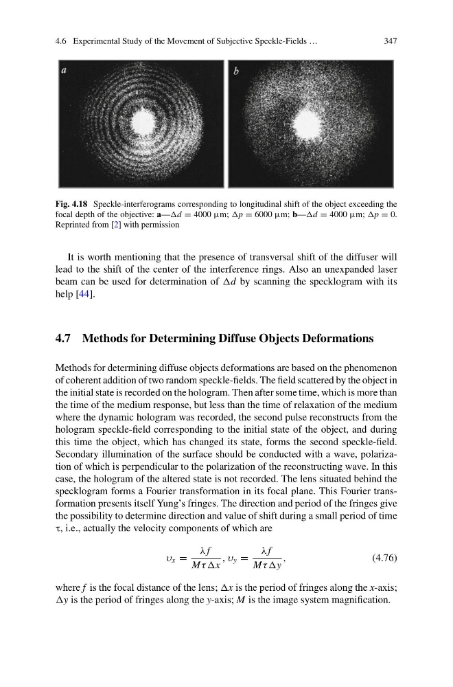
Fig. 4.18 Speckle-interferograms corresponding to longitudinal shift of the object exceeding the
focal depth of the objective: a—d = 4000 μm; p = 6000 μm; b—d = 4000 μm; p = 0.
Reprinted from [2] with permission
It is worth mentioning that the presence of transversal shift of the diffuser will
lead to the shift of the center of the interference rings. Also an unexpanded laser
beam can be used for determination of d by scanning the specklogram with its
help [44].
4.7 Methods for Determining Diffuse Objects Deformations
Methods for determining diffuse objects deformations are based on the phenomenon
of coherent addition of two random speckle-fields. The field scattered by the object in
the initial state is recorded on the hologram. Then after some time, which is more than
the time of the medium response, but less than the time of relaxation of the medium
where the dynamic hologram was recorded, the second pulse reconstructs from the
hologram speckle-field corresponding to the initial state of the object, and during
this time the object, which has changed its state, forms the second speckle-field.
Secondary illumination of the surface should be conducted with a wave, polarization of which is perpendicular to the polarization of the reconstructing wave. In this
case, the hologram of the altered state is not recorded. The lens situated behind the
specklogram forms a Fourier transformation in its focal plane. This Fourier transformation presents itself Yung’s fringes. The direction and period of the fringes give
the possibility to determine direction and value of shift during a small period of time
τ, i.e., actually the velocity components of which are
υ x =
λ f
Mτ τx
, υ y =
λ f
Mτ τy
,
(4.76)
where f is the focal distance of the lens; x is the period of fringes along the x-axis;
y is the period of fringes along the y-axis; M is the image system magnification.
347
Fig. 4.18 Speckle-interferograms corresponding to longitudinal shift of the object exceeding the
focal depth of the objective: a—d = 4000 μm; p = 6000 μm; b—d = 4000 μm; p = 0.
Reprinted from [2] with permission
It is worth mentioning that the presence of transversal shift of the diffuser will
lead to the shift of the center of the interference rings. Also an unexpanded laser
beam can be used for determination of d by scanning the specklogram with its
help [44].
4.7 Methods for Determining Diffuse Objects Deformations
Methods for determining diffuse objects deformations are based on the phenomenon
of coherent addition of two random speckle-fields. The field scattered by the object in
the initial state is recorded on the hologram. Then after some time, which is more than
the time of the medium response, but less than the time of relaxation of the medium
where the dynamic hologram was recorded, the second pulse reconstructs from the
hologram speckle-field corresponding to the initial state of the object, and during
this time the object, which has changed its state, forms the second speckle-field.
Secondary illumination of the surface should be conducted with a wave, polarization of which is perpendicular to the polarization of the reconstructing wave. In this
case, the hologram of the altered state is not recorded. The lens situated behind the
specklogram forms a Fourier transformation in its focal plane. This Fourier transformation presents itself Yung’s fringes. The direction and period of the fringes give
the possibility to determine direction and value of shift during a small period of time
τ, i.e., actually the velocity components of which are
υ x =
λ f
Mτ τx
, υ y =
λ f
Mτ τy
,
(4.76)
where f is the focal distance of the lens; x is the period of fringes along the x-axis;
y is the period of fringes along the y-axis; M is the image system magnification.