

346
4 Speckle-Optical Methods and Devices for Studying …
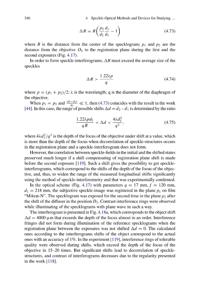
R = R
p 2
d 2
d 1
d 1
− 1
(4.73)
where R is the distance from the center of the specklogram; p 1 and p 2 are the
distance from the objective O b to the registration plane during the first and the
second exposures (Fig. 4.17).
In order to form speckle-interferograms, R must exceed the average size of the
speckles
R >
1.22λp
q
(4.74)
where p = ( p 1 + p 2 )/2; λ is the wavelength; q is the diameter of the diaphragm of
the objective.
When p 1 = p 2 and
(d2−d1)
d 2
1, then (4.73) coincides with the result in the work
[44]. In this case, the range of possible shifts d = d 2 – d 1 is determined by the ratio
1.22λpd 2
q R
<
2
1
q 2 ,
(4.75)
where 4λd
2
1 /q
2 is the depth of the focus of the objective under shift at a value, which
is more than the depth of the focus when decorrelation of speckle-structures occurs
in the registration plane and a speckle-interferogram does not form.
However, the correlation between speckle-fields in the initial and the shifted states
preserved much longer if a shift compensating of registration plane shift is made
before the second exposure [119]. Such a shift gives the possibility to get speckleinterferograms, which correspond to the shifts of the depth of the focus of the objective, and, thus, to widen the range of the measured longitudinal shifts significantly
using the method of speckle-interferometry and that was experimentally confirmed.
In the optical scheme (Fig. 4.17) with parameters q = 17 mm, f = 120 mm,
d 1 = 218 mm, the subjective speckle-image was registered in the plane p 1 on film
“Mikrat-N”. The specklogram was exposed for the second time in the plane p 2 after
the shift of the diffuser in the position D 2 . Contrast interference rings were observed
while illuminating of the specklograms with plane wave in such a way.
The interferogram is presented in Fig. 4.18a, which corresponds to the object shift
d = 4000 μm that exceeds the depth of the focus almost in an order. Interference
fringes did not form during illumination of the reference specklograms when the
registration plane between the exposures was not shifted d = 0. The calculated
ones according to the interferograms shifts of the object correspond to the actual
ones with an accuracy of 1%. In the experiment [119], interference rings of tolerable
quality were observed during shifts, which exceed the depth of the focus of the
objective in 15–20 times. But significant shifts lead to decorrelation of specklestructures, and contrast of interferograms decreases due to the regularity presented
in the work [118].
4 Speckle-Optical Methods and Devices for Studying …
R = R
p 2
d 2
d 1
d 1
− 1
(4.73)
where R is the distance from the center of the specklogram; p 1 and p 2 are the
distance from the objective O b to the registration plane during the first and the
second exposures (Fig. 4.17).
In order to form speckle-interferograms, R must exceed the average size of the
speckles
R >
1.22λp
q
(4.74)
where p = ( p 1 + p 2 )/2; λ is the wavelength; q is the diameter of the diaphragm of
the objective.
When p 1 = p 2 and
(d2−d1)
d 2
1, then (4.73) coincides with the result in the work
[44]. In this case, the range of possible shifts d = d 2 – d 1 is determined by the ratio
1.22λpd 2
q R
<
2
1
q 2 ,
(4.75)
where 4λd
2
1 /q
2 is the depth of the focus of the objective under shift at a value, which
is more than the depth of the focus when decorrelation of speckle-structures occurs
in the registration plane and a speckle-interferogram does not form.
However, the correlation between speckle-fields in the initial and the shifted states
preserved much longer if a shift compensating of registration plane shift is made
before the second exposure [119]. Such a shift gives the possibility to get speckleinterferograms, which correspond to the shifts of the depth of the focus of the objective, and, thus, to widen the range of the measured longitudinal shifts significantly
using the method of speckle-interferometry and that was experimentally confirmed.
In the optical scheme (Fig. 4.17) with parameters q = 17 mm, f = 120 mm,
d 1 = 218 mm, the subjective speckle-image was registered in the plane p 1 on film
“Mikrat-N”. The specklogram was exposed for the second time in the plane p 2 after
the shift of the diffuser in the position D 2 . Contrast interference rings were observed
while illuminating of the specklograms with plane wave in such a way.
The interferogram is presented in Fig. 4.18a, which corresponds to the object shift
d = 4000 μm that exceeds the depth of the focus almost in an order. Interference
fringes did not form during illumination of the reference specklograms when the
registration plane between the exposures was not shifted d = 0. The calculated
ones according to the interferograms shifts of the object correspond to the actual
ones with an accuracy of 1%. In the experiment [119], interference rings of tolerable
quality were observed during shifts, which exceed the depth of the focus of the
objective in 15–20 times. But significant shifts lead to decorrelation of specklestructures, and contrast of interferograms decreases due to the regularity presented
in the work [118].