

4.2 Application of Spectral Characteristics of Dynamic Speckle-Field …
331
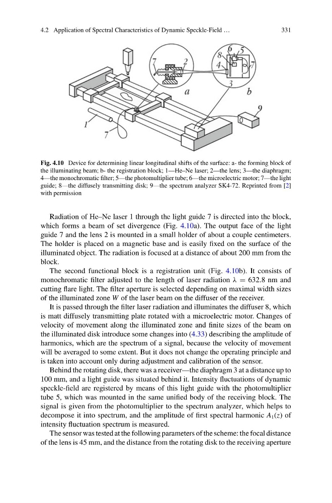
Fig. 4.10 Device for determining linear longitudinal shifts of the surface: a- the forming block of
the illuminating beam; b- the registration block; 1—He–Ne laser; 2—the lens; 3—the diaphragm;
4—the monochromatic filter; 5—the photomultiplier tube; 6—the microelectric motor; 7—the light
guide; 8—the diffusely transmitting disk; 9—the spectrum analyzer SK4-72. Reprinted from [2]
with permission
Radiation of He–Ne laser 1 through the light guide 7 is directed into the block,
which forms a beam of set divergence (Fig. 4.10a). The output face of the light
guide 7 and the lens 2 is mounted in a small holder of about a couple centimeters.
The holder is placed on a magnetic base and is easily fixed on the surface of the
illuminated object. The radiation is focused at a distance of about 200 mm from the
block.
The second functional block is a registration unit (Fig. 4.10b). It consists of
monochromatic filter adjusted to the length of laser radiation λ = 632.8 nm and
cutting flare light. The filter aperture is selected depending on maximal width sizes
of the illuminated zone W of the laser beam on the diffuser of the receiver.
It is passed through the filter laser radiation and illuminates the diffuser 8, which
is matt diffusely transmitting plate rotated with a microelectric motor. Changes of
velocity of movement along the illuminated zone and finite sizes of the beam on
the illuminated disk introduce some changes into (4.33) describing the amplitude of
harmonics, which are the spectrum of a signal, because the velocity of movement
will be averaged to some extent. But it does not change the operating principle and
is taken into account only during adjustment and calibration of the sensor.
Behind the rotating disk, there was a receiver—the diaphragm 3 at a distance up to
100 mm, and a light guide was situated behind it. Intensity fluctuations of dynamic
speckle-field are registered by means of this light guide with the photomultiplier
tube 5, which was mounted in the same unified body of the receiving block. The
signal is given from the photomultiplier to the spectrum analyzer, which helps to
decompose it into spectrum, and the amplitude of first spectral harmonic A 1 (z) of
intensity fluctuation spectrum is measured.
The sensor was tested at the following parameters of the scheme: the focal distance
of the lens is 45 mm, and the distance from the rotating disk to the receiving aperture
331
Fig. 4.10 Device for determining linear longitudinal shifts of the surface: a- the forming block of
the illuminating beam; b- the registration block; 1—He–Ne laser; 2—the lens; 3—the diaphragm;
4—the monochromatic filter; 5—the photomultiplier tube; 6—the microelectric motor; 7—the light
guide; 8—the diffusely transmitting disk; 9—the spectrum analyzer SK4-72. Reprinted from [2]
with permission
Radiation of He–Ne laser 1 through the light guide 7 is directed into the block,
which forms a beam of set divergence (Fig. 4.10a). The output face of the light
guide 7 and the lens 2 is mounted in a small holder of about a couple centimeters.
The holder is placed on a magnetic base and is easily fixed on the surface of the
illuminated object. The radiation is focused at a distance of about 200 mm from the
block.
The second functional block is a registration unit (Fig. 4.10b). It consists of
monochromatic filter adjusted to the length of laser radiation λ = 632.8 nm and
cutting flare light. The filter aperture is selected depending on maximal width sizes
of the illuminated zone W of the laser beam on the diffuser of the receiver.
It is passed through the filter laser radiation and illuminates the diffuser 8, which
is matt diffusely transmitting plate rotated with a microelectric motor. Changes of
velocity of movement along the illuminated zone and finite sizes of the beam on
the illuminated disk introduce some changes into (4.33) describing the amplitude of
harmonics, which are the spectrum of a signal, because the velocity of movement
will be averaged to some extent. But it does not change the operating principle and
is taken into account only during adjustment and calibration of the sensor.
Behind the rotating disk, there was a receiver—the diaphragm 3 at a distance up to
100 mm, and a light guide was situated behind it. Intensity fluctuations of dynamic
speckle-field are registered by means of this light guide with the photomultiplier
tube 5, which was mounted in the same unified body of the receiving block. The
signal is given from the photomultiplier to the spectrum analyzer, which helps to
decompose it into spectrum, and the amplitude of first spectral harmonic A 1 (z) of
intensity fluctuation spectrum is measured.
The sensor was tested at the following parameters of the scheme: the focal distance
of the lens is 45 mm, and the distance from the rotating disk to the receiving aperture