

258
3 Holographic Interferometry for Studying …
of recording and reconstructing beams. The reconstruction of the double-exposure
hologram is conducted with the continuous He–Ne laser.
The chest image with the interference pattern is produced on the receiving area of
the registration system with the optical system of interferogram formation. Using the
block of electronic processing and connection with computer the image is analogdigitally processed, then it is inputted into the computer and then outputted onto
the display for visual estimation of the interference pattern. Quantities of shifts and
speeds of point on the surface under study are calculated using a computer.
To increase the accuracy and reliability of measurements, it is suggested that
the interferograms are processed in the phase regime. To do this and to provide the
determination of shift directions under formation of recording beams, the first and
the second ruby laser radiation pulses should spread in different directions.
This can be reached with a special device of spatial separation of recording
beams, which should be activated by the sync pulse from the synchronization system.
Besides, it is necessary to provide phase modulation of one of the reconstructing
beams due to the harmonic law with a set frequency.
Then the electrical signal, which is registered in the point of the image, can be
written as follows
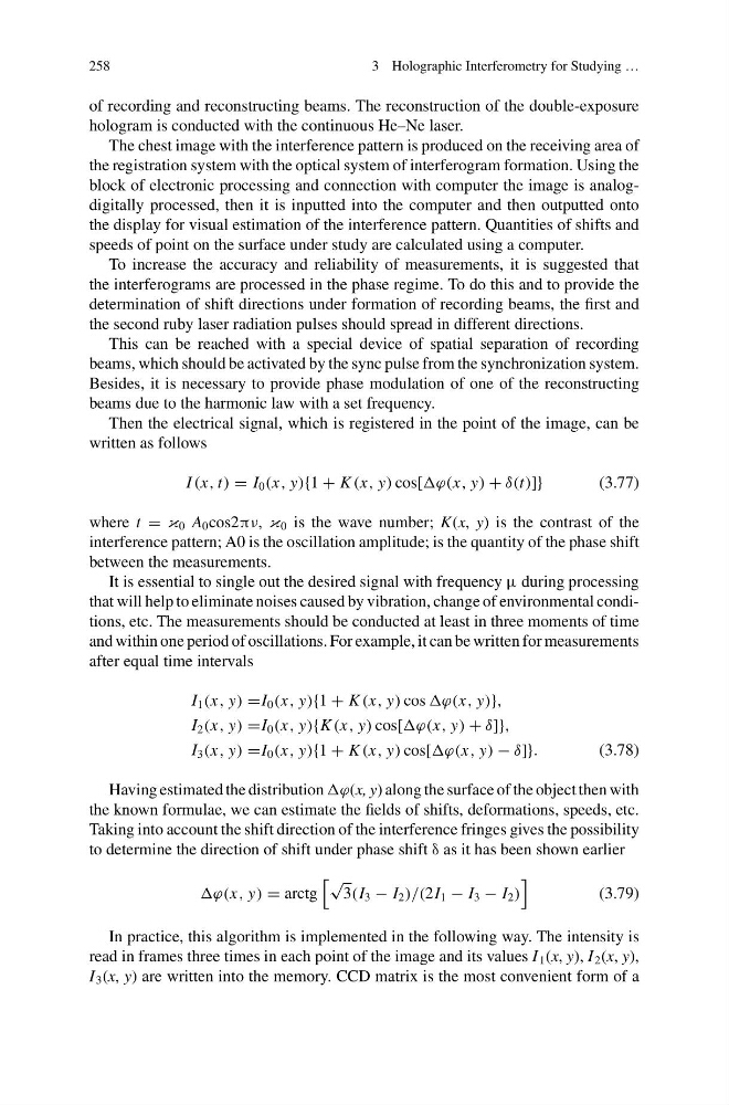
I (x, t) = I 0 (x, y){1 + K (x, y) cos[ϕ(x, y) + δ(t)]}
(3.77)
where t = κ 0 A 0 cos2πν, κ 0 is the wave number; K(x, y) is the contrast of the
interference pattern; A0 is the oscillation amplitude; is the quantity of the phase shift
between the measurements.
It is essential to single out the desired signal with frequency μ during processing
that will help to eliminate noises caused by vibration, change of environmental conditions, etc. The measurements should be conducted at least in three moments of time
and within one period of oscillations. For example, it can be written for measurements
after equal time intervals
I 1 (x, y) =I 0 (x, y){1 + K (x, y) cos ϕ(x, y)},
I 2 (x, y) =I 0 (x, y){K (x, y) cos[ϕ(x, y) + δ]},
I 3 (x, y) =I 0 (x, y){1 + K (x, y) cos[ϕ(x, y) − δ]}.
(3.78)
Having estimated the distribution ϕ(x, y) along the surface of the object then with
the known formulae, we can estimate the fields of shifts, deformations, speeds, etc.
Taking into account the shift direction of the interference fringes gives the possibility
to determine the direction of shift under phase shift δ as it has been shown earlier
ϕ(x, y) = arctg
√
3(I 3 − I 2 )/(2I 1 − I 3 − I 2 )
(3.79)
In practice, this algorithm is implemented in the following way. The intensity is
read in frames three times in each point of the image and its values I 1 (x, y), I 2 (x, y),
I 3 (x, y) are written into the memory. CCD matrix is the most convenient form of a
3 Holographic Interferometry for Studying …
of recording and reconstructing beams. The reconstruction of the double-exposure
hologram is conducted with the continuous He–Ne laser.
The chest image with the interference pattern is produced on the receiving area of
the registration system with the optical system of interferogram formation. Using the
block of electronic processing and connection with computer the image is analogdigitally processed, then it is inputted into the computer and then outputted onto
the display for visual estimation of the interference pattern. Quantities of shifts and
speeds of point on the surface under study are calculated using a computer.
To increase the accuracy and reliability of measurements, it is suggested that
the interferograms are processed in the phase regime. To do this and to provide the
determination of shift directions under formation of recording beams, the first and
the second ruby laser radiation pulses should spread in different directions.
This can be reached with a special device of spatial separation of recording
beams, which should be activated by the sync pulse from the synchronization system.
Besides, it is necessary to provide phase modulation of one of the reconstructing
beams due to the harmonic law with a set frequency.
Then the electrical signal, which is registered in the point of the image, can be
written as follows
I (x, t) = I 0 (x, y){1 + K (x, y) cos[ϕ(x, y) + δ(t)]}
(3.77)
where t = κ 0 A 0 cos2πν, κ 0 is the wave number; K(x, y) is the contrast of the
interference pattern; A0 is the oscillation amplitude; is the quantity of the phase shift
between the measurements.
It is essential to single out the desired signal with frequency μ during processing
that will help to eliminate noises caused by vibration, change of environmental conditions, etc. The measurements should be conducted at least in three moments of time
and within one period of oscillations. For example, it can be written for measurements
after equal time intervals
I 1 (x, y) =I 0 (x, y){1 + K (x, y) cos ϕ(x, y)},
I 2 (x, y) =I 0 (x, y){K (x, y) cos[ϕ(x, y) + δ]},
I 3 (x, y) =I 0 (x, y){1 + K (x, y) cos[ϕ(x, y) − δ]}.
(3.78)
Having estimated the distribution ϕ(x, y) along the surface of the object then with
the known formulae, we can estimate the fields of shifts, deformations, speeds, etc.
Taking into account the shift direction of the interference fringes gives the possibility
to determine the direction of shift under phase shift δ as it has been shown earlier
ϕ(x, y) = arctg
√
3(I 3 − I 2 )/(2I 1 − I 3 − I 2 )
(3.79)
In practice, this algorithm is implemented in the following way. The intensity is
read in frames three times in each point of the image and its values I 1 (x, y), I 2 (x, y),
I 3 (x, y) are written into the memory. CCD matrix is the most convenient form of a