

230
3 Holographic Interferometry for Studying …
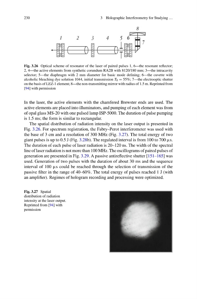
Fig. 3.26 Optical scheme of resonator of the laser of paired pulses 1, 6—the resonant reflector;
2, 4—the active elements from synthetic corundum RA2B with 8120/180 mm; 3—the intracavity
selector; 5—the diaphragm with 2 mm diameter for basic mode defining; 6—the cuvette with
alcoholic bleaching dye solution 1044, initial transmission T 0 = 55%; 7—the electrooptic shutter
on the basis of LEZ-1 element; 8—the non-transmitting mirror with radius of 1.5 m. Reprinted from
[94] with permission
In the laser, the active elements with the chamfered Brewster ends are used. The
active elements are placed into illuminators, and pumping of each element was from
of opal glass MS-20 with one pulsed lamp ISP-5000. The duration of pulse pumping
is 1.5 ms; the form is similar to rectangular.
The spatial distribution of radiation intensity on the laser output is presented in
Fig. 3.26. For spectrum registration, the Fabry–Perot interferometer was used with
the base of 3 cm and a resolution of 300 MHz (Fig. 3.27). The total energy of two
giant pulses is up to 0.5 J (Fig. 3.28b). The regulated interval is from 100 to 700 μs.
The duration of each pulse of laser radiation is 20–120 ns. The width of the spectral
line of laser radiation is not more than 100 MHz. The oscillograms of paired pulses of
generation are presented in Fig. 3.29. A passive antireflective shutter [151–165] was
used. Generation of two pulses with the duration of about 30 ms and the sequence
interval of 100 μs could be reached through the selection of transmission of the
passive filter in the range of 40–60%. The total energy of pulses reached 1 J (with
an amplifier). Regimes of hologram recording and processing were optimized.
Fig. 3.27 Spatial
distribution of radiation
intensity at the laser output.
Reprinted from [94] with
permission
3 Holographic Interferometry for Studying …
Fig. 3.26 Optical scheme of resonator of the laser of paired pulses 1, 6—the resonant reflector;
2, 4—the active elements from synthetic corundum RA2B with 8120/180 mm; 3—the intracavity
selector; 5—the diaphragm with 2 mm diameter for basic mode defining; 6—the cuvette with
alcoholic bleaching dye solution 1044, initial transmission T 0 = 55%; 7—the electrooptic shutter
on the basis of LEZ-1 element; 8—the non-transmitting mirror with radius of 1.5 m. Reprinted from
[94] with permission
In the laser, the active elements with the chamfered Brewster ends are used. The
active elements are placed into illuminators, and pumping of each element was from
of opal glass MS-20 with one pulsed lamp ISP-5000. The duration of pulse pumping
is 1.5 ms; the form is similar to rectangular.
The spatial distribution of radiation intensity on the laser output is presented in
Fig. 3.26. For spectrum registration, the Fabry–Perot interferometer was used with
the base of 3 cm and a resolution of 300 MHz (Fig. 3.27). The total energy of two
giant pulses is up to 0.5 J (Fig. 3.28b). The regulated interval is from 100 to 700 μs.
The duration of each pulse of laser radiation is 20–120 ns. The width of the spectral
line of laser radiation is not more than 100 MHz. The oscillograms of paired pulses of
generation are presented in Fig. 3.29. A passive antireflective shutter [151–165] was
used. Generation of two pulses with the duration of about 30 ms and the sequence
interval of 100 μs could be reached through the selection of transmission of the
passive filter in the range of 40–60%. The total energy of pulses reached 1 J (with
an amplifier). Regimes of hologram recording and processing were optimized.
Fig. 3.27 Spatial
distribution of radiation
intensity at the laser output.
Reprinted from [94] with
permission