

220
3 Holographic Interferometry for Studying …
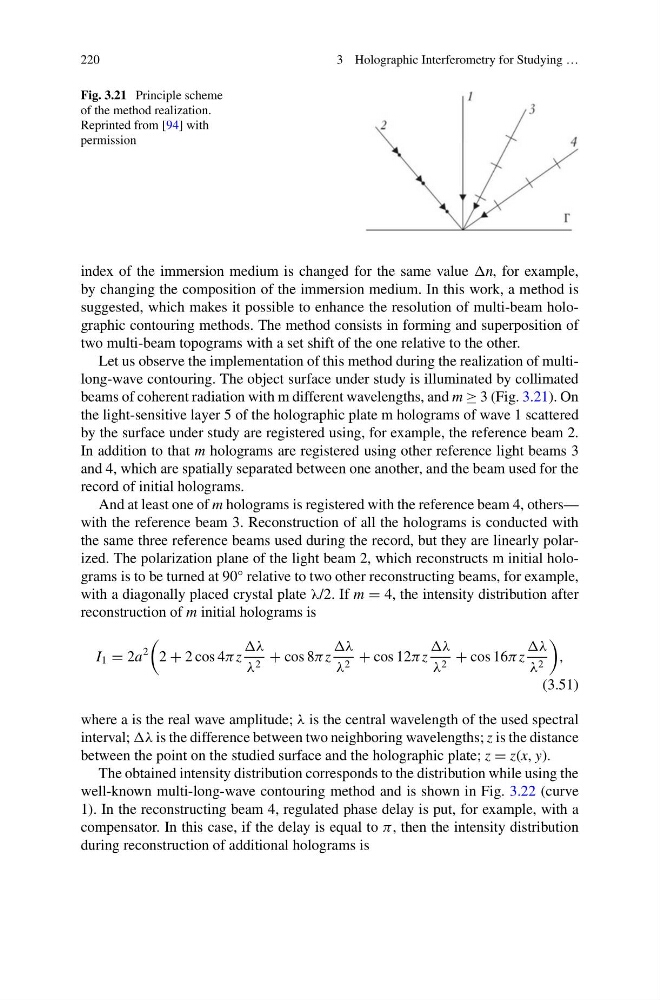
Fig. 3.21 Principle scheme
of the method realization.
Reprinted from [94] with
permission
index of the immersion medium is changed for the same value n, for example,
by changing the composition of the immersion medium. In this work, a method is
suggested, which makes it possible to enhance the resolution of multi-beam holographic contouring methods. The method consists in forming and superposition of
two multi-beam topograms with a set shift of the one relative to the other.
Let us observe the implementation of this method during the realization of multilong-wave contouring. The object surface under study is illuminated by collimated
beams of coherent radiation with m different wavelengths, and m ≥ 3 (Fig. 3.21). On
the light-sensitive layer 5 of the holographic plate m holograms of wave 1 scattered
by the surface under study are registered using, for example, the reference beam 2.
In addition to that m holograms are registered using other reference light beams 3
and 4, which are spatially separated between one another, and the beam used for the
record of initial holograms.
And at least one of m holograms is registered with the reference beam 4, others—
with the reference beam 3. Reconstruction of all the holograms is conducted with
the same three reference beams used during the record, but they are linearly polarized. The polarization plane of the light beam 2, which reconstructs m initial holograms is to be turned at 90° relative to two other reconstructing beams, for example,
with a diagonally placed crystal plate λ/2. If m = 4, the intensity distribution after
reconstruction of m initial holograms is
I 1 = 2a
2
2 + 2 cos 4π z
λ
λ 2 + cos 8π z
λ
λ 2 + cos 12π z
λ
λ 2 + cos 16π z
λ
λ 2
,
(3.51)
where a is the real wave amplitude; λ is the central wavelength of the used spectral
interval; λ is the difference between two neighboring wavelengths; z is the distance
between the point on the studied surface and the holographic plate; z = z(x, y).
The obtained intensity distribution corresponds to the distribution while using the
well-known multi-long-wave contouring method and is shown in Fig. 3.22 (curve
1). In the reconstructing beam 4, regulated phase delay is put, for example, with a
compensator. In this case, if the delay is equal to π, then the intensity distribution
during reconstruction of additional holograms is
3 Holographic Interferometry for Studying …
Fig. 3.21 Principle scheme
of the method realization.
Reprinted from [94] with
permission
index of the immersion medium is changed for the same value n, for example,
by changing the composition of the immersion medium. In this work, a method is
suggested, which makes it possible to enhance the resolution of multi-beam holographic contouring methods. The method consists in forming and superposition of
two multi-beam topograms with a set shift of the one relative to the other.
Let us observe the implementation of this method during the realization of multilong-wave contouring. The object surface under study is illuminated by collimated
beams of coherent radiation with m different wavelengths, and m ≥ 3 (Fig. 3.21). On
the light-sensitive layer 5 of the holographic plate m holograms of wave 1 scattered
by the surface under study are registered using, for example, the reference beam 2.
In addition to that m holograms are registered using other reference light beams 3
and 4, which are spatially separated between one another, and the beam used for the
record of initial holograms.
And at least one of m holograms is registered with the reference beam 4, others—
with the reference beam 3. Reconstruction of all the holograms is conducted with
the same three reference beams used during the record, but they are linearly polarized. The polarization plane of the light beam 2, which reconstructs m initial holograms is to be turned at 90° relative to two other reconstructing beams, for example,
with a diagonally placed crystal plate λ/2. If m = 4, the intensity distribution after
reconstruction of m initial holograms is
I 1 = 2a
2
2 + 2 cos 4π z
λ
λ 2 + cos 8π z
λ
λ 2 + cos 12π z
λ
λ 2 + cos 16π z
λ
λ 2
,
(3.51)
where a is the real wave amplitude; λ is the central wavelength of the used spectral
interval; λ is the difference between two neighboring wavelengths; z is the distance
between the point on the studied surface and the holographic plate; z = z(x, y).
The obtained intensity distribution corresponds to the distribution while using the
well-known multi-long-wave contouring method and is shown in Fig. 3.22 (curve
1). In the reconstructing beam 4, regulated phase delay is put, for example, with a
compensator. In this case, if the delay is equal to π, then the intensity distribution
during reconstruction of additional holograms is