

2.4 Development and Improvement of the Holographic Interference …
151
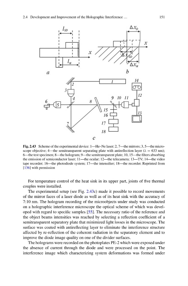
Fig. 2.43 Scheme of the experimental device: 1—He–Ne laser; 2, 7—the mirrors; 3, 5—the microscope objective; 4—the semitransparent separating plate with antireflection layer (λ = 633 nm);
6—the test specimen; 8—the hologram; 9—the semitransparent plate; 10, 15—the filters absorbing
the emission of semiconductor laser; 11—the ocular; 12—the telecamera; 13—TV; 14—the video
tape recorder; 16—the photodiode system; 17—the intensifier; 18—the recorder. Reprinted from
[136] with permission
For temperature control of the heat sink in its upper part, joints of five thermal
couples were installed.
The experimental setup (see Fig. 2.43c) made it possible to record movements
of the mirror faces of a laser diode as well as of its heat sink with the accuracy of
7:10 nm. The hologram recording of the microobjects under study was conducted
on a holographic interference microscope the optical scheme of which was developed with regard to specific samples [55]. The necessary ratio of the reference and
the object beams intensities was reached by selecting a reflection coefficient of a
semitransparent separatory plate that minimized light losses in the microscope. The
surface was coated with antireflecting layer to eliminate the interference structure
affected by re-reflection of the coherent radiation in the separatory element and to
improve the diode image quality on one of the divider surfaces.
The holograms were recorded on the photoplates PE-2 which were exposed under
the absence of current through the diode and were processed on the point. The
interference image which characterizing system deformations was formed under
151
Fig. 2.43 Scheme of the experimental device: 1—He–Ne laser; 2, 7—the mirrors; 3, 5—the microscope objective; 4—the semitransparent separating plate with antireflection layer (λ = 633 nm);
6—the test specimen; 8—the hologram; 9—the semitransparent plate; 10, 15—the filters absorbing
the emission of semiconductor laser; 11—the ocular; 12—the telecamera; 13—TV; 14—the video
tape recorder; 16—the photodiode system; 17—the intensifier; 18—the recorder. Reprinted from
[136] with permission
For temperature control of the heat sink in its upper part, joints of five thermal
couples were installed.
The experimental setup (see Fig. 2.43c) made it possible to record movements
of the mirror faces of a laser diode as well as of its heat sink with the accuracy of
7:10 nm. The hologram recording of the microobjects under study was conducted
on a holographic interference microscope the optical scheme of which was developed with regard to specific samples [55]. The necessary ratio of the reference and
the object beams intensities was reached by selecting a reflection coefficient of a
semitransparent separatory plate that minimized light losses in the microscope. The
surface was coated with antireflecting layer to eliminate the interference structure
affected by re-reflection of the coherent radiation in the separatory element and to
improve the diode image quality on one of the divider surfaces.
The holograms were recorded on the photoplates PE-2 which were exposed under
the absence of current through the diode and were processed on the point. The
interference image which characterizing system deformations was formed under