

2.2 Basic Models of Quasi-Steady Laser Welding
27
where: a, b—The half-axis lengths of the double ellipsoid model in the x and y
directions, respectively. The focal radius of laser beam is used.
c—The half-axis length of the double ellipsoid model in the z direction. The
effective depth of heat source is used.
Therefore, the study proposes the rotating Gauss heat source in the upper part of
the workpiece and the double ellipsoid heat source model in the lower part of the
workpiece. The body heat source mode means that the heat flow acts directly on the
metal inside the material, enabling the keyhole to form rapidly. These keyhole effects
are considerably different from those produced when heat source acts only on the
surface of the metal surface. As far as the physical nature of heat transfer in deep
penetration laser welding is concerned, the combination heat source is the progress
and development of the combination heat source composed of surface heat source
and columnar heat source.
2.3 Implementation of Numerical Solution
2.3.1 Upwind Scheme
The upwind scheme appeared in the 1950s and has been developing ever since. It was
initially proposed by Courant, Issacson and Rees, and later on, was re-expounded by
Gentry, Martin and Daly, Barakat and Clark, Runchal and Wolfsh-tein, etc. It gives
full consideration to the influence of the flow direction on the derivative difference
calculation formula and the function value-taking method on the interface.
(1) Definition of Taylor expansion method
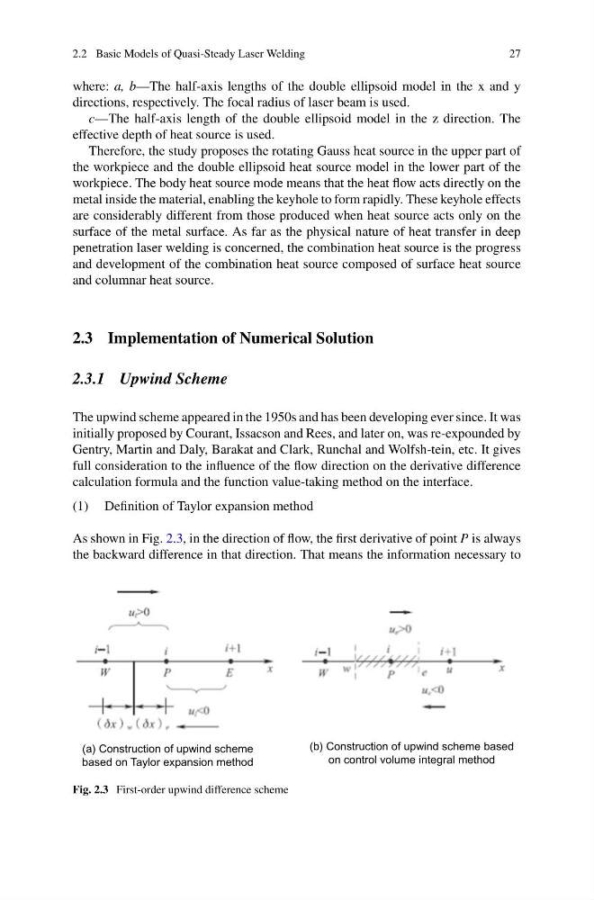
As shown in Fig. 2.3, in the direction of flow, the first derivative of point P is always
the backward difference in that direction. That means the information necessary to
(a) Construction of upwind scheme
based on Taylor expansion method
(b) Construction of upwind scheme based
on control volume integral method
Fig. 2.3 First-order upwind difference scheme
27
where: a, b—The half-axis lengths of the double ellipsoid model in the x and y
directions, respectively. The focal radius of laser beam is used.
c—The half-axis length of the double ellipsoid model in the z direction. The
effective depth of heat source is used.
Therefore, the study proposes the rotating Gauss heat source in the upper part of
the workpiece and the double ellipsoid heat source model in the lower part of the
workpiece. The body heat source mode means that the heat flow acts directly on the
metal inside the material, enabling the keyhole to form rapidly. These keyhole effects
are considerably different from those produced when heat source acts only on the
surface of the metal surface. As far as the physical nature of heat transfer in deep
penetration laser welding is concerned, the combination heat source is the progress
and development of the combination heat source composed of surface heat source
and columnar heat source.
2.3 Implementation of Numerical Solution
2.3.1 Upwind Scheme
The upwind scheme appeared in the 1950s and has been developing ever since. It was
initially proposed by Courant, Issacson and Rees, and later on, was re-expounded by
Gentry, Martin and Daly, Barakat and Clark, Runchal and Wolfsh-tein, etc. It gives
full consideration to the influence of the flow direction on the derivative difference
calculation formula and the function value-taking method on the interface.
(1) Definition of Taylor expansion method
As shown in Fig. 2.3, in the direction of flow, the first derivative of point P is always
the backward difference in that direction. That means the information necessary to
(a) Construction of upwind scheme
based on Taylor expansion method
(b) Construction of upwind scheme based
on control volume integral method
Fig. 2.3 First-order upwind difference scheme