

8.3 Keyhole and Weld Pool Dynamics in Welding with Filler Wires
211
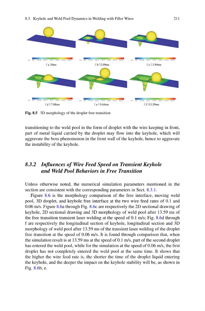
Fig. 8.5 3D morphology of the droplet free transition
transitioning to the weld pool in the form of droplet with the wire keeping in front,
part of metal liquid carried by the droplet may flow into the keyhole, which will
aggravate the boss phenomenon in the front wall of the keyhole, hence to aggravate
the instability of the keyhole.
8.3.2 Influences of Wire Feed Speed on Transient Keyhole
and Weld Pool Behaviors in Free Transition
Unless otherwise noted, the numerical simulation parameters mentioned in the
section are consistent with the corresponding parameters in Sect. 8.3.1.
Figure 8.6 is the morphology comparison of the free interface, moving weld
pool, 3D droplet, and keyhole free interface at the two wire feed rates of 0.1 and
0.06 m/s. Figure 8.6a through Fig. 8.6c are respectively the 2D sectional drawing of
keyhole, 2D sectional drawing and 3D morphology of weld pool after 13.59 ms of
the free transition transient laser welding at the speed of 0.1 m/s; Fig. 8.6d through
f are respectively the longitudinal section of keyhole, longitudinal section and 3D
morphology of weld pool after 13.59 ms of the transient laser welding of the droplet
free transition at the speed of 0.06 m/s. It is found through comparison that, when
the simulation result is at 13.59 ms at the speed of 0.1 m/s, part of the second droplet
has entered the weld pool, while for the simulation at the speed of 0.06 m/s, the first
droplet has not completely entered the weld pool at the same time. It shows that
the higher the wire feed rate is, the shorter the time of the droplet liquid entering
the keyhole, and the deeper the impact on the keyhole stability will be, as shown in
Fig. 8.6b, e.
211
Fig. 8.5 3D morphology of the droplet free transition
transitioning to the weld pool in the form of droplet with the wire keeping in front,
part of metal liquid carried by the droplet may flow into the keyhole, which will
aggravate the boss phenomenon in the front wall of the keyhole, hence to aggravate
the instability of the keyhole.
8.3.2 Influences of Wire Feed Speed on Transient Keyhole
and Weld Pool Behaviors in Free Transition
Unless otherwise noted, the numerical simulation parameters mentioned in the
section are consistent with the corresponding parameters in Sect. 8.3.1.
Figure 8.6 is the morphology comparison of the free interface, moving weld
pool, 3D droplet, and keyhole free interface at the two wire feed rates of 0.1 and
0.06 m/s. Figure 8.6a through Fig. 8.6c are respectively the 2D sectional drawing of
keyhole, 2D sectional drawing and 3D morphology of weld pool after 13.59 ms of
the free transition transient laser welding at the speed of 0.1 m/s; Fig. 8.6d through
f are respectively the longitudinal section of keyhole, longitudinal section and 3D
morphology of weld pool after 13.59 ms of the transient laser welding of the droplet
free transition at the speed of 0.06 m/s. It is found through comparison that, when
the simulation result is at 13.59 ms at the speed of 0.1 m/s, part of the second droplet
has entered the weld pool, while for the simulation at the speed of 0.06 m/s, the first
droplet has not completely entered the weld pool at the same time. It shows that
the higher the wire feed rate is, the shorter the time of the droplet liquid entering
the keyhole, and the deeper the impact on the keyhole stability will be, as shown in
Fig. 8.6b, e.