

178
6 Behaviors of Keyhole and Weld Pool Under the Effect …
(a) General view
(b) Upper part of keyhole
(c) Lower part of keyhole
(d) Middle part of keyhole (metallic
vapor inside keyhole considered)
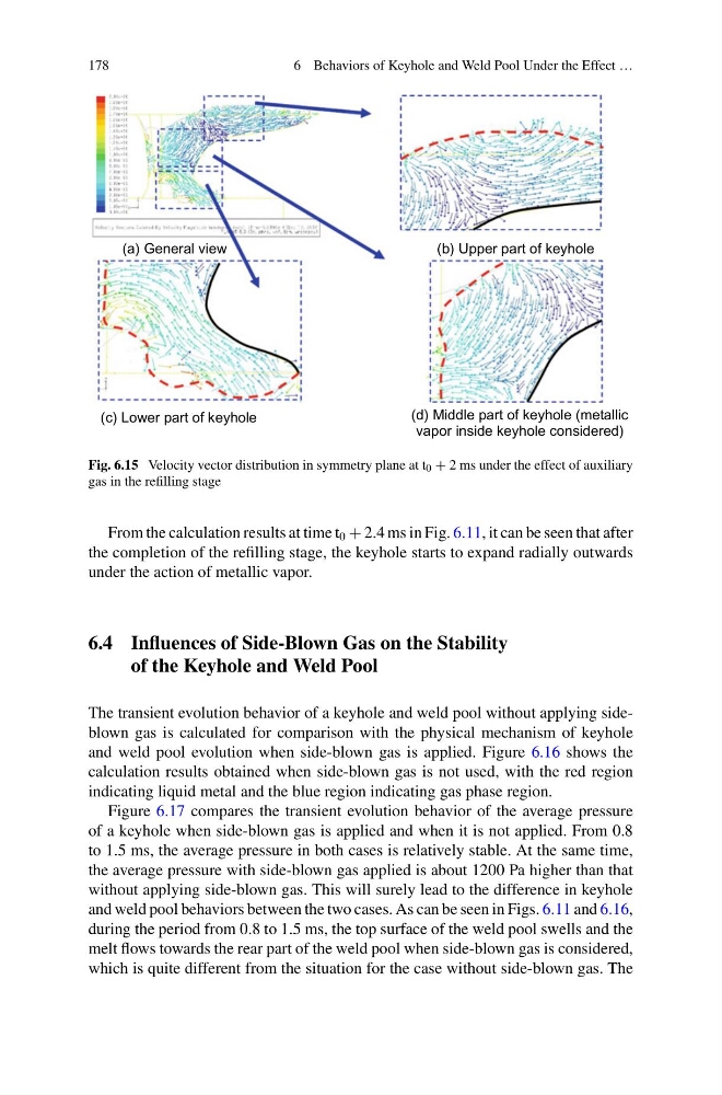
Fig. 6.15 Velocity vector distribution in symmetry plane at t 0 + 2 ms under the effect of auxiliary
gas in the refilling stage
From the calculation results at time t 0 + 2.4 ms in Fig. 6.11, it can be seen that after
the completion of the refilling stage, the keyhole starts to expand radially outwards
under the action of metallic vapor.
6.4 Influences of Side-Blown Gas on the Stability
of the Keyhole and Weld Pool
The transient evolution behavior of a keyhole and weld pool without applying sideblown gas is calculated for comparison with the physical mechanism of keyhole
and weld pool evolution when side-blown gas is applied. Figure 6.16 shows the
calculation results obtained when side-blown gas is not used, with the red region
indicating liquid metal and the blue region indicating gas phase region.
Figure 6.17 compares the transient evolution behavior of the average pressure
of a keyhole when side-blown gas is applied and when it is not applied. From 0.8
to 1.5 ms, the average pressure in both cases is relatively stable. At the same time,
the average pressure with side-blown gas applied is about 1200 Pa higher than that
without applying side-blown gas. This will surely lead to the difference in keyhole
and weld pool behaviors between the two cases. As can be seen in Figs. 6.11 and 6.16,
during the period from 0.8 to 1.5 ms, the top surface of the weld pool swells and the
melt flows towards the rear part of the weld pool when side-blown gas is considered,
which is quite different from the situation for the case without side-blown gas. The
6 Behaviors of Keyhole and Weld Pool Under the Effect …
(a) General view
(b) Upper part of keyhole
(c) Lower part of keyhole
(d) Middle part of keyhole (metallic
vapor inside keyhole considered)
Fig. 6.15 Velocity vector distribution in symmetry plane at t 0 + 2 ms under the effect of auxiliary
gas in the refilling stage
From the calculation results at time t 0 + 2.4 ms in Fig. 6.11, it can be seen that after
the completion of the refilling stage, the keyhole starts to expand radially outwards
under the action of metallic vapor.
6.4 Influences of Side-Blown Gas on the Stability
of the Keyhole and Weld Pool
The transient evolution behavior of a keyhole and weld pool without applying sideblown gas is calculated for comparison with the physical mechanism of keyhole
and weld pool evolution when side-blown gas is applied. Figure 6.16 shows the
calculation results obtained when side-blown gas is not used, with the red region
indicating liquid metal and the blue region indicating gas phase region.
Figure 6.17 compares the transient evolution behavior of the average pressure
of a keyhole when side-blown gas is applied and when it is not applied. From 0.8
to 1.5 ms, the average pressure in both cases is relatively stable. At the same time,
the average pressure with side-blown gas applied is about 1200 Pa higher than that
without applying side-blown gas. This will surely lead to the difference in keyhole
and weld pool behaviors between the two cases. As can be seen in Figs. 6.11 and 6.16,
during the period from 0.8 to 1.5 ms, the top surface of the weld pool swells and the
melt flows towards the rear part of the weld pool when side-blown gas is considered,
which is quite different from the situation for the case without side-blown gas. The