

86
3 Modeling Composite Structures
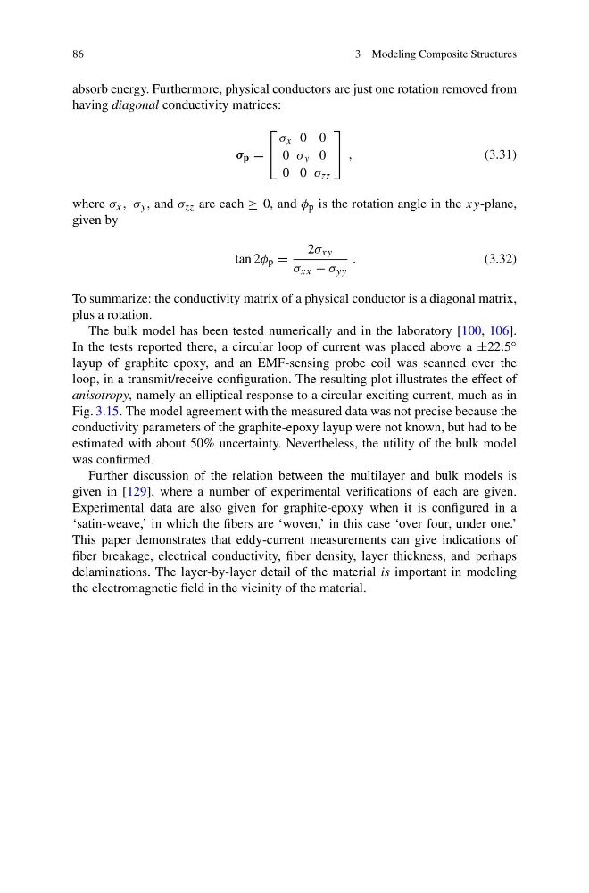
absorb energy. Furthermore, physical conductors are just one rotation removed from
having diagonal conductivity matrices:
σ p =
⎡
⎣
σ x 0 0
0 σ y 0
0 0 σ zz
⎤
⎦ ,
(3.31)
where σ x , σ y , and σ zz are each ≥ 0, and φ p is the rotation angle in the xy-plane,
given by
tan 2φ p =
2σ xy
σ xx − σ yy
.
(3.32)
To summarize: the conductivity matrix of a physical conductor is a diagonal matrix,
plus a rotation.
The bulk model has been tested numerically and in the laboratory [100, 106].
In the tests reported there, a circular loop of current was placed above a ±22.5 ◦
layup of graphite epoxy, and an EMF-sensing probe coil was scanned over the
loop, in a transmit/receive configuration. The resulting plot illustrates the effect of
anisotropy, namely an elliptical response to a circular exciting current, much as in
Fig. 3.15. The model agreement with the measured data was not precise because the
conductivity parameters of the graphite-epoxy layup were not known, but had to be
estimated with about 50% uncertainty. Nevertheless, the utility of the bulk model
was confirmed.
Further discussion of the relation between the multilayer and bulk models is
given in [129], where a number of experimental verifications of each are given.
Experimental data are also given for graphite-epoxy when it is configured in a
‘satin-weave,’ in which the fibers are ‘woven,’ in this case ‘over four, under one.’
This paper demonstrates that eddy-current measurements can give indications of
fiber breakage, electrical conductivity, fiber density, layer thickness, and perhaps
delaminations. The layer-by-layer detail of the material is important in modeling
the electromagnetic field in the vicinity of the material.
3 Modeling Composite Structures
absorb energy. Furthermore, physical conductors are just one rotation removed from
having diagonal conductivity matrices:
σ p =
⎡
⎣
σ x 0 0
0 σ y 0
0 0 σ zz
⎤
⎦ ,
(3.31)
where σ x , σ y , and σ zz are each ≥ 0, and φ p is the rotation angle in the xy-plane,
given by
tan 2φ p =
2σ xy
σ xx − σ yy
.
(3.32)
To summarize: the conductivity matrix of a physical conductor is a diagonal matrix,
plus a rotation.
The bulk model has been tested numerically and in the laboratory [100, 106].
In the tests reported there, a circular loop of current was placed above a ±22.5 ◦
layup of graphite epoxy, and an EMF-sensing probe coil was scanned over the
loop, in a transmit/receive configuration. The resulting plot illustrates the effect of
anisotropy, namely an elliptical response to a circular exciting current, much as in
Fig. 3.15. The model agreement with the measured data was not precise because the
conductivity parameters of the graphite-epoxy layup were not known, but had to be
estimated with about 50% uncertainty. Nevertheless, the utility of the bulk model
was confirmed.
Further discussion of the relation between the multilayer and bulk models is
given in [129], where a number of experimental verifications of each are given.
Experimental data are also given for graphite-epoxy when it is configured in a
‘satin-weave,’ in which the fibers are ‘woven,’ in this case ‘over four, under one.’
This paper demonstrates that eddy-current measurements can give indications of
fiber breakage, electrical conductivity, fiber density, layer thickness, and perhaps
delaminations. The layer-by-layer detail of the material is important in modeling
the electromagnetic field in the vicinity of the material.