

3.4 A Coupled-Circuit Model of Maxwell’s Equations
67
3.4 A Coupled-Circuit Model of Maxwell’s Equations
Maxwell’s dual equations are
∇ × E = −jωμ 0 (H + M)
∇ × H = jωωE + σ E ,
(3.2)
where the first equation is Faraday’s law, and the second Ampere’s circuital law. We
call these ‘dual equations,’ in the sense that the sources of the first are magnetic
currents, and those of the second are electric currents. In representing fields by
means of electric circuits, we use duality in the same way. In a circuit, we would
represent the sum of magnetic effects (voltages) by a series circuit, since voltages
add in such a circuit, and the sum of electric currents by a parallel circuit, since
currents add in such a circuit.
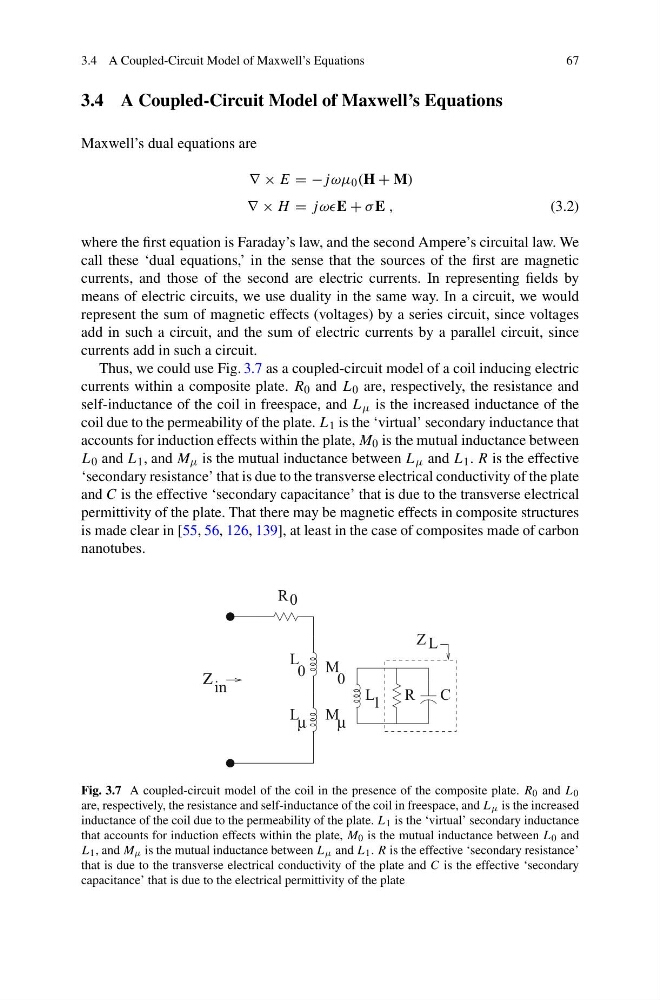
Thus, we could use Fig. 3.7 as a coupled-circuit model of a coil inducing electric
currents within a composite plate. R 0 and L 0 are, respectively, the resistance and
self-inductance of the coil in freespace, and L μ is the increased inductance of the
coil due to the permeability of the plate. L 1 is the ‘virtual’ secondary inductance that
accounts for induction effects within the plate, M 0 is the mutual inductance between
L 0 and L 1 , and M μ is the mutual inductance between L μ and L 1 . R is the effective
‘secondary resistance’ that is due to the transverse electrical conductivity of the plate
and C is the effective ‘secondary capacitance’ that is due to the transverse electrical
permittivity of the plate. That there may be magnetic effects in composite structures
is made clear in [55, 56, 126, 139], at least in the case of composites made of carbon
nanotubes.
0
R
L
0
L μ
L 1 R
0
M
M μ
in
Ζ
C
Z L
Fig. 3.7 A coupled-circuit model of the coil in the presence of the composite plate. R 0 and L 0
are, respectively, the resistance and self-inductance of the coil in freespace, and L μ is the increased
inductance of the coil due to the permeability of the plate. L 1 is the ‘virtual’ secondary inductance
that accounts for induction effects within the plate, M 0 is the mutual inductance between L 0 and
L 1 , and M μ is the mutual inductance between L μ and L 1 . R is the effective ‘secondary resistance’
that is due to the transverse electrical conductivity of the plate and C is the effective ‘secondary
capacitance’ that is due to the electrical permittivity of the plate
67
3.4 A Coupled-Circuit Model of Maxwell’s Equations
Maxwell’s dual equations are
∇ × E = −jωμ 0 (H + M)
∇ × H = jωωE + σ E ,
(3.2)
where the first equation is Faraday’s law, and the second Ampere’s circuital law. We
call these ‘dual equations,’ in the sense that the sources of the first are magnetic
currents, and those of the second are electric currents. In representing fields by
means of electric circuits, we use duality in the same way. In a circuit, we would
represent the sum of magnetic effects (voltages) by a series circuit, since voltages
add in such a circuit, and the sum of electric currents by a parallel circuit, since
currents add in such a circuit.
Thus, we could use Fig. 3.7 as a coupled-circuit model of a coil inducing electric
currents within a composite plate. R 0 and L 0 are, respectively, the resistance and
self-inductance of the coil in freespace, and L μ is the increased inductance of the
coil due to the permeability of the plate. L 1 is the ‘virtual’ secondary inductance that
accounts for induction effects within the plate, M 0 is the mutual inductance between
L 0 and L 1 , and M μ is the mutual inductance between L μ and L 1 . R is the effective
‘secondary resistance’ that is due to the transverse electrical conductivity of the plate
and C is the effective ‘secondary capacitance’ that is due to the transverse electrical
permittivity of the plate. That there may be magnetic effects in composite structures
is made clear in [55, 56, 126, 139], at least in the case of composites made of carbon
nanotubes.
0
R
L
0
L μ
L 1 R
0
M
M μ
in
Ζ
C
Z L
Fig. 3.7 A coupled-circuit model of the coil in the presence of the composite plate. R 0 and L 0
are, respectively, the resistance and self-inductance of the coil in freespace, and L μ is the increased
inductance of the coil due to the permeability of the plate. L 1 is the ‘virtual’ secondary inductance
that accounts for induction effects within the plate, M 0 is the mutual inductance between L 0 and
L 1 , and M μ is the mutual inductance between L μ and L 1 . R is the effective ‘secondary resistance’
that is due to the transverse electrical conductivity of the plate and C is the effective ‘secondary
capacitance’ that is due to the electrical permittivity of the plate