

332
12 Carbon-Nanotube Reinforced Polymers
12.8 Inverse Problems
12.8.1 Inverse Problem No. 1
Piezoresisivity manifests itself quantum-mechanically through the change, due to
material strain, in the band-gap between the valence and conduction bands. If, as we
assume, the atomic-orbital wave functions that go into the conductivity expression,
(12.3), depend upon the band structure, then it follows that the conductivity can
be directly computed as a function of strain from (12.3). This means that we can
determine the state of strain throughout a region of the structure by determining the
conductivity throughout that region. This is a classical problem of ’eddy-current’
nondestructive evaluation (NDE) by either model-based inversion or voxel-based
inversion [111]. This is what VIC-3D® was designed to solve. The inclusion of
quantum models such as (12.3)into VIC-3D® is under development.
The inversion is a two-step process. First, we generate a family of red curves as
in Fig. 12.2, each parameterized by a known value of band-gap. Depending upon
the frequency of excitation of the ‘eddy-current’ probe, we may use much of the
frequency range of Fig. 12.2, or more likely frequencies that are essentially DC. We
create an interpolation table with given values of band-gap, and generate ‘forward
responses’ for the measured impedance using the given σ (ω) corresponding to the
nodal values of band-gap in the interpolation table. The forward response table,
which we will call the ‘surrogate model’, is computed using VIC-3D® with the
appropriate σ (ω). If the frequency range is large, then σ (ω) will not be constant, and
we will develop a new data type for VIC-3D® to accomodate frequency-dependent
electromagnetic parameters.
Once we have inverted the measured impedance data to determine the bandgap, we must still go through a second step to infer the strain. The procedure is
reasonably straightforward, and we paraphrase the theoretical model described in
[29], which is also based on a tight-binding model. The change in the band-gap for
small strains is given by
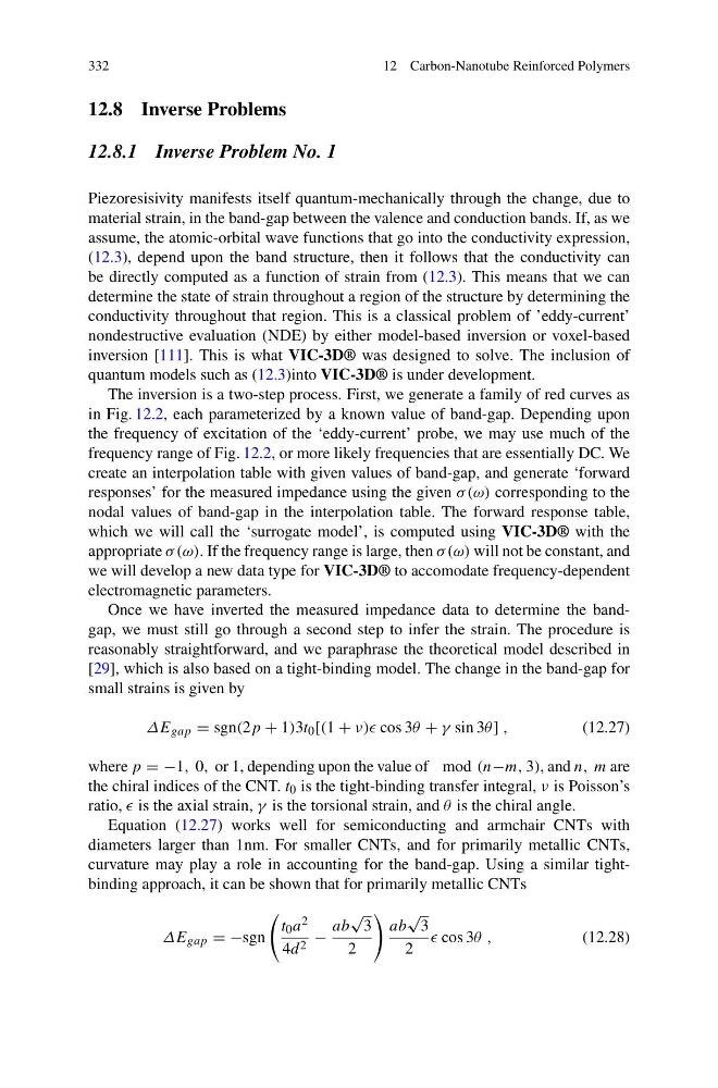
ΔE gap = sgn(2p + 1)3t 0 [(1 + ν)) cos 3θ + γ sin 3θ ] ,
(12.27)
where p = −1, 0, or 1, depending upon the value of mod (n−m, 3), and n, m are
the chiral indices of the CNT. t 0 is the tight-binding transfer integral, ν is Poisson’s
ratio, is the axial strain, γ is the torsional strain, and θ is the chiral angle.
Equation (12.27) works well for semiconducting and armchair CNTs with
diameters larger than 1nm. For smaller CNTs, and for primarily metallic CNTs,
curvature may play a role in accounting for the band-gap. Using a similar tightbinding approach, it can be shown that for primarily metallic CNTs
ΔE gap = −sgn
t 0 a 2
4d 2 −
ab
√
3
2
ab
√
3
2
cos 3θ ,
(12.28)
12 Carbon-Nanotube Reinforced Polymers
12.8 Inverse Problems
12.8.1 Inverse Problem No. 1
Piezoresisivity manifests itself quantum-mechanically through the change, due to
material strain, in the band-gap between the valence and conduction bands. If, as we
assume, the atomic-orbital wave functions that go into the conductivity expression,
(12.3), depend upon the band structure, then it follows that the conductivity can
be directly computed as a function of strain from (12.3). This means that we can
determine the state of strain throughout a region of the structure by determining the
conductivity throughout that region. This is a classical problem of ’eddy-current’
nondestructive evaluation (NDE) by either model-based inversion or voxel-based
inversion [111]. This is what VIC-3D® was designed to solve. The inclusion of
quantum models such as (12.3)into VIC-3D® is under development.
The inversion is a two-step process. First, we generate a family of red curves as
in Fig. 12.2, each parameterized by a known value of band-gap. Depending upon
the frequency of excitation of the ‘eddy-current’ probe, we may use much of the
frequency range of Fig. 12.2, or more likely frequencies that are essentially DC. We
create an interpolation table with given values of band-gap, and generate ‘forward
responses’ for the measured impedance using the given σ (ω) corresponding to the
nodal values of band-gap in the interpolation table. The forward response table,
which we will call the ‘surrogate model’, is computed using VIC-3D® with the
appropriate σ (ω). If the frequency range is large, then σ (ω) will not be constant, and
we will develop a new data type for VIC-3D® to accomodate frequency-dependent
electromagnetic parameters.
Once we have inverted the measured impedance data to determine the bandgap, we must still go through a second step to infer the strain. The procedure is
reasonably straightforward, and we paraphrase the theoretical model described in
[29], which is also based on a tight-binding model. The change in the band-gap for
small strains is given by
ΔE gap = sgn(2p + 1)3t 0 [(1 + ν)) cos 3θ + γ sin 3θ ] ,
(12.27)
where p = −1, 0, or 1, depending upon the value of mod (n−m, 3), and n, m are
the chiral indices of the CNT. t 0 is the tight-binding transfer integral, ν is Poisson’s
ratio, is the axial strain, γ is the torsional strain, and θ is the chiral angle.
Equation (12.27) works well for semiconducting and armchair CNTs with
diameters larger than 1nm. For smaller CNTs, and for primarily metallic CNTs,
curvature may play a role in accounting for the band-gap. Using a similar tightbinding approach, it can be shown that for primarily metallic CNTs
ΔE gap = −sgn
t 0 a 2
4d 2 −
ab
√
3
2
ab
√
3
2
cos 3θ ,
(12.28)