

2 Bio-microelectromechanical Systems (BioMEMS) …
55
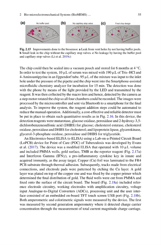
Fig. 2.15 Improvements done to the biosensor. a Leak from vent holes by not having buffer pools.
b Small leak in the chip without the capillary stop valves. c No leakage by having the buffer pool
and capillary stop valves (Li et al. 2019c)
The chip could then be sealed into a vacuum pouch and stored for 6 months at 4 °C.
In order to test the system, 10 μL of serum was mixed with 190 μL of Tris–HCl and
4-Aminoantipyrine in an Eppendorf tube. 95 μL of the mixture was input to the inlet
hole under the pressure of the pipette and the chip went into the Smartphone-assisted
microfluidic chemistry analyzer for incubation for 15 min. The detection was done
with the phone by means of the light provided by the LED and transmitted by the
reagent. It was then collected by the macro lens and hence, detected by the camera as
a step motor rotated the chip so all four chambers could be recorded. The images were
processed by the microcontroller and sent via Bluetooth to a smartphone for the final
analysis. To improve the system, the reagent addition steps could be automated to
reduce the manual operation. Additionally, a cost-effective and reliable detector must
be put in place to obtain such quantitative results as in Fig. 2.16. In this device, the
detection reagents were mutarotase, glucose oxidase, peroxidase and 2-hydroxy-3,5dichlorobenzenesulfonic acid (DHBS) for glucose; cholesterol esterase, cholesterol
oxidase, peroxidase and DHBS for cholesterol; and lipoprotein lipase, glycerokinase,
glycerol-3-phosphate oxidase, peroxidase and DHBS for triglyceride.
An Electronics-based ELISA (e-ELISA) using a Lab-on-a-Printed Circuit Board
(LoPCB) device for Point of Care (POC) of Tuberculosis was developed by Evans
et al. (2017). The device was a modified ELISA that operated with 10 μL volume
and included PMMA wells, gold surface, TMB as the reporter reagent (Fig. 2.17a)
and Interferon Gamma (IFNγ), a pro-inflammatory cytokine key in innate and
acquired immunity, as the assay target. Copper (Cu) foil was laminated to the FR4
PCB substrate through thermal adhesion. Subsequently, tracks made from electrical
connections, and electrode pads were patterned by etching the Cu layer. A gold
layer was plated on top of the copper one and was fixed by the copper primer which
determined the final distribution of gold. The fluid wells were cut from PMMA and
fixed onto the surface of the circuit board. The board (Fig. 2.18a) included reference electrode circuitry, working electrodes with amplification circuitry, voltage
input Analogue-to-Digital Converters (ADCs), processing unit and the user interface consisted of an embedded on-board TFT touch screen USB port (Fig. 2.18b).
Both amperometric and colorimetric signals were measured by the device. The first
was measured by second generation amperometry where it detected charge carrier
concentration through the measurement of total current magnitude charge carriage.
55
Fig. 2.15 Improvements done to the biosensor. a Leak from vent holes by not having buffer pools.
b Small leak in the chip without the capillary stop valves. c No leakage by having the buffer pool
and capillary stop valves (Li et al. 2019c)
The chip could then be sealed into a vacuum pouch and stored for 6 months at 4 °C.
In order to test the system, 10 μL of serum was mixed with 190 μL of Tris–HCl and
4-Aminoantipyrine in an Eppendorf tube. 95 μL of the mixture was input to the inlet
hole under the pressure of the pipette and the chip went into the Smartphone-assisted
microfluidic chemistry analyzer for incubation for 15 min. The detection was done
with the phone by means of the light provided by the LED and transmitted by the
reagent. It was then collected by the macro lens and hence, detected by the camera as
a step motor rotated the chip so all four chambers could be recorded. The images were
processed by the microcontroller and sent via Bluetooth to a smartphone for the final
analysis. To improve the system, the reagent addition steps could be automated to
reduce the manual operation. Additionally, a cost-effective and reliable detector must
be put in place to obtain such quantitative results as in Fig. 2.16. In this device, the
detection reagents were mutarotase, glucose oxidase, peroxidase and 2-hydroxy-3,5dichlorobenzenesulfonic acid (DHBS) for glucose; cholesterol esterase, cholesterol
oxidase, peroxidase and DHBS for cholesterol; and lipoprotein lipase, glycerokinase,
glycerol-3-phosphate oxidase, peroxidase and DHBS for triglyceride.
An Electronics-based ELISA (e-ELISA) using a Lab-on-a-Printed Circuit Board
(LoPCB) device for Point of Care (POC) of Tuberculosis was developed by Evans
et al. (2017). The device was a modified ELISA that operated with 10 μL volume
and included PMMA wells, gold surface, TMB as the reporter reagent (Fig. 2.17a)
and Interferon Gamma (IFNγ), a pro-inflammatory cytokine key in innate and
acquired immunity, as the assay target. Copper (Cu) foil was laminated to the FR4
PCB substrate through thermal adhesion. Subsequently, tracks made from electrical
connections, and electrode pads were patterned by etching the Cu layer. A gold
layer was plated on top of the copper one and was fixed by the copper primer which
determined the final distribution of gold. The fluid wells were cut from PMMA and
fixed onto the surface of the circuit board. The board (Fig. 2.18a) included reference electrode circuitry, working electrodes with amplification circuitry, voltage
input Analogue-to-Digital Converters (ADCs), processing unit and the user interface consisted of an embedded on-board TFT touch screen USB port (Fig. 2.18b).
Both amperometric and colorimetric signals were measured by the device. The first
was measured by second generation amperometry where it detected charge carrier
concentration through the measurement of total current magnitude charge carriage.