

172
A. S. Cerda-Kipper and S. Hosseini
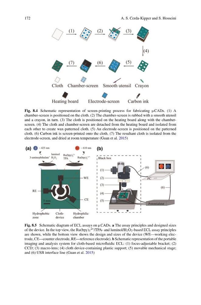
Fig. 8.4 Schematic representation of screen-printing process for fabricating µCADs. (1) A
chamber-screen is positioned on the cloth. (2) The chamber-screen is rubbed with a smooth utensil
and a crayon, in turn. (3) The cloth is positioned on the heating board along with the chamberscreen. (4) The cloth and chamber-screen are detached from the heating board and isolated from
each other to create wax-patterned cloth. (5) An electrode-screen is positioned on the patterned
cloth. (6) Carbon ink is screen-printed onto the cloth. (7) The resultant cloth is isolated from the
electrode-screen, and dried at room temperature (Guan et al. 2015)
Fig. 8.5 Schematic diagram of ECL assays on µCADs. a The assay principles and designed sizes
of the device. In the top view, the Ru(bpy) 3
2+ /TPA- and luminol/H 2 O 2 -based ECL assay principles
are shown, while the bottom view shows the design and sizes of the device (WE—working electrode, CE—counter electrode, RE—reference electrode). b Schematic representation of the portable
imaging and analysis system for cloth-based microfluidic ECL: (1) focus-adjustable bracket; (2)
CCD; (3) macro-lens; (4) cloth device-containing plastic support; (5) movable mechanical stage;
and (6) USB interface line (Guan et al. 2015)
A. S. Cerda-Kipper and S. Hosseini
Fig. 8.4 Schematic representation of screen-printing process for fabricating µCADs. (1) A
chamber-screen is positioned on the cloth. (2) The chamber-screen is rubbed with a smooth utensil
and a crayon, in turn. (3) The cloth is positioned on the heating board along with the chamberscreen. (4) The cloth and chamber-screen are detached from the heating board and isolated from
each other to create wax-patterned cloth. (5) An electrode-screen is positioned on the patterned
cloth. (6) Carbon ink is screen-printed onto the cloth. (7) The resultant cloth is isolated from the
electrode-screen, and dried at room temperature (Guan et al. 2015)
Fig. 8.5 Schematic diagram of ECL assays on µCADs. a The assay principles and designed sizes
of the device. In the top view, the Ru(bpy) 3
2+ /TPA- and luminol/H 2 O 2 -based ECL assay principles
are shown, while the bottom view shows the design and sizes of the device (WE—working electrode, CE—counter electrode, RE—reference electrode). b Schematic representation of the portable
imaging and analysis system for cloth-based microfluidic ECL: (1) focus-adjustable bracket; (2)
CCD; (3) macro-lens; (4) cloth device-containing plastic support; (5) movable mechanical stage;
and (6) USB interface line (Guan et al. 2015)