

118
A. S. Cerda-Kipper and S. Hosseini
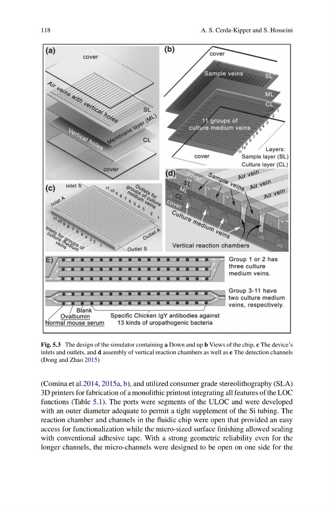
Fig. 5.3 The design of the simulator containing a Down and up b Views of the chip, c The device’s
inlets and outlets, and d assembly of vertical reaction chambers as well as e The detection channels
(Dong and Zhao 2015)
(Comina et al.2014, 2015a, b), and utilized consumer grade stereolithography (SLA)
3D printers for fabrication of a monolithic printout integrating all features of the LOC
functions (Table 5.1). The ports were segments of the ULOC and were developed
with an outer diameter adequate to permit a tight supplement of the Si tubing. The
reaction chamber and channels in the fluidic chip were open that provided an easy
access for functionalization while the micro-sized surface finishing allowed sealing
with conventional adhesive tape. With a strong geometric reliability even for the
longer channels, the micro-channels were designed to be open on one side for the
A. S. Cerda-Kipper and S. Hosseini
Fig. 5.3 The design of the simulator containing a Down and up b Views of the chip, c The device’s
inlets and outlets, and d assembly of vertical reaction chambers as well as e The detection channels
(Dong and Zhao 2015)
(Comina et al.2014, 2015a, b), and utilized consumer grade stereolithography (SLA)
3D printers for fabrication of a monolithic printout integrating all features of the LOC
functions (Table 5.1). The ports were segments of the ULOC and were developed
with an outer diameter adequate to permit a tight supplement of the Si tubing. The
reaction chamber and channels in the fluidic chip were open that provided an easy
access for functionalization while the micro-sized surface finishing allowed sealing
with conventional adhesive tape. With a strong geometric reliability even for the
longer channels, the micro-channels were designed to be open on one side for the