

3.4 Experimental Implementation of RP-THz-TDS
57
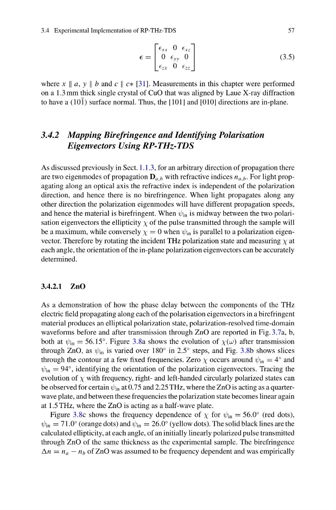
=
⎡
⎣
xx 0 xz
0 yy 0
zx 0 zz
⎤
⎦
(3.5)
where x a, y b and c c∗ [31]. Measurements in this chapter were performed
on a 1.3 mm thick single crystal of CuO that was aligned by Laue X-ray diffraction
to have a (10 ¯
1) surface normal. Thus, the [101] and [010] directions are in-plane.
3.4.2 Mapping Birefringence and Identifying Polarisation
Eigenvectors Using RP-THz-TDS
As discussed previously in Sect. 1.1.3, for an arbitrary direction of propagation there
are two eigenmodes of propagation D a,b with refractive indices n a,b . For light propagating along an optical axis the refractive index is independent of the polarization
direction, and hence there is no birefringence. When light propagates along any
other direction the polarization eigenmodes will have different propagation speeds,
and hence the material is birefringent. When ψ in is midway between the two polarisation eigenvectors the ellipticity χ of the pulse transmitted through the sample will
be a maximum, while conversely χ = 0 when ψ in is parallel to a polarization eigenvector. Therefore by rotating the incident THz polarization state and measuring χ at
each angle, the orientation of the in-plane polarization eigenvectors can be accurately
determined.
3.4.2.1 ZnO
As a demonstration of how the phase delay between the components of the THz
electric field propagating along each of the polarisation eigenvectors in a birefringent
material produces an elliptical polarization state, polarization-resolved time-domain
waveforms before and after transmission through ZnO are reported in Fig. 3.7a, b,
both at ψ in = 56.15
◦ . Figure 3.8a shows the evolution of χ(ω) after transmission
through ZnO, as ψ in is varied over 180
◦ in 2.5
◦ steps, and Fig. 3.8b shows slices
through the contour at a few fixed frequencies. Zero χ occurs around ψ in = 4
◦ and
ψ in = 94
◦ , identifying the orientation of the polarization eigenvectors. Tracing the
evolution of χ with frequency, right- and left-handed circularly polarized states can
be observed for certain ψ in at 0.75 and 2.25 THz, where the ZnO is acting as a quarterwave plate, and between these frequencies the polarization state becomes linear again
at 1.5 THz, where the ZnO is acting as a half-wave plate.
Figure 3.8c shows the frequency dependence of χ for ψ in = 56.0
◦ (red dots),
ψ in = 71.0
◦ (orange dots) and ψ in = 26.0
◦ (yellow dots). The solid black lines are the
calculated ellipticity, at each angle, of an initially linearly polarized pulse transmitted
through ZnO of the same thickness as the experimental sample. The birefringence
n = n a − n b of ZnO was assumed to be frequency dependent and was empirically
57
=
⎡
⎣
xx 0 xz
0 yy 0
zx 0 zz
⎤
⎦
(3.5)
where x a, y b and c c∗ [31]. Measurements in this chapter were performed
on a 1.3 mm thick single crystal of CuO that was aligned by Laue X-ray diffraction
to have a (10 ¯
1) surface normal. Thus, the [101] and [010] directions are in-plane.
3.4.2 Mapping Birefringence and Identifying Polarisation
Eigenvectors Using RP-THz-TDS
As discussed previously in Sect. 1.1.3, for an arbitrary direction of propagation there
are two eigenmodes of propagation D a,b with refractive indices n a,b . For light propagating along an optical axis the refractive index is independent of the polarization
direction, and hence there is no birefringence. When light propagates along any
other direction the polarization eigenmodes will have different propagation speeds,
and hence the material is birefringent. When ψ in is midway between the two polarisation eigenvectors the ellipticity χ of the pulse transmitted through the sample will
be a maximum, while conversely χ = 0 when ψ in is parallel to a polarization eigenvector. Therefore by rotating the incident THz polarization state and measuring χ at
each angle, the orientation of the in-plane polarization eigenvectors can be accurately
determined.
3.4.2.1 ZnO
As a demonstration of how the phase delay between the components of the THz
electric field propagating along each of the polarisation eigenvectors in a birefringent
material produces an elliptical polarization state, polarization-resolved time-domain
waveforms before and after transmission through ZnO are reported in Fig. 3.7a, b,
both at ψ in = 56.15
◦ . Figure 3.8a shows the evolution of χ(ω) after transmission
through ZnO, as ψ in is varied over 180
◦ in 2.5
◦ steps, and Fig. 3.8b shows slices
through the contour at a few fixed frequencies. Zero χ occurs around ψ in = 4
◦ and
ψ in = 94
◦ , identifying the orientation of the polarization eigenvectors. Tracing the
evolution of χ with frequency, right- and left-handed circularly polarized states can
be observed for certain ψ in at 0.75 and 2.25 THz, where the ZnO is acting as a quarterwave plate, and between these frequencies the polarization state becomes linear again
at 1.5 THz, where the ZnO is acting as a half-wave plate.
Figure 3.8c shows the frequency dependence of χ for ψ in = 56.0
◦ (red dots),
ψ in = 71.0
◦ (orange dots) and ψ in = 26.0
◦ (yellow dots). The solid black lines are the
calculated ellipticity, at each angle, of an initially linearly polarized pulse transmitted
through ZnO of the same thickness as the experimental sample. The birefringence
n = n a − n b of ZnO was assumed to be frequency dependent and was empirically