

2.2 Electro-optic Sampling
31
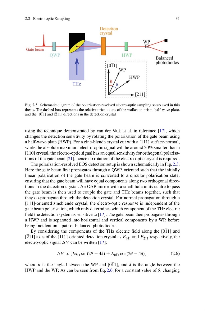
Fig. 2.3 Schematic diagram of the polarisation-resolved electro-optic sampling setup used in this
thesis. The dashed box represents the relative orientations of the wollaston prism, half-wave plate,
and the [011] and [211] directions in the detection crystal
using the technique demonstrated by van der Valk et al. in reference [17], which
changes the detection sensitivity by rotating the polarisation of the gate beam using
a half-wave plate (HWP). For a zinc-blende crystal cut with a [111] surface-normal,
while the absolute maximum electro-optic signal will be around 20% smaller than a
[110] crystal, the electro-optic signal has an equal sensitivity for orthogonal polarisations of the gate beam [21], hence no rotation of the electro-optic crystal is required.
The polarisation-resolved EOS detection setup is shown schematically in Fig. 2.3.
Here the gate beam first propagates through a QWP, oriented such that the initially
linear polarisation of the gate beam is converted to a circular polarisation state,
ensuring that the gate beam will have equal components along two orthogonal directions in the detection crystal. An OAP mirror with a small hole in its centre to pass
the gate beam is then used to couple the gate and THz beams together, such that
they co-propagate through the detection crystal. For normal propagation through a
[111]-oriented zincblende crystal, the electro-optic response is independent of the
gate beam polarisation, which only determines which component of the THz electric
field the detection system is sensitive to [17]. The gate beam then propagates through
a HWP and is separated into horizontal and vertical components by a WP, before
being incident on a pair of balanced photodiodes.
By considering the components of the THz electric field along the [011] and
[211] axes of the [111]-oriented detection crystal as E 011 and E 211 respectively, the
electro-optic signal V can be written [17]:
V ∝ [E 211 sin(2θ − 4δ) + E 011 cos(2θ − 4δ)],
(2.6)
where θ is the angle between the WP and [011], and δ is the angle between the
HWP and the WP. As can be seen from Eq. 2.6, for a constant value of θ , changing
31
Fig. 2.3 Schematic diagram of the polarisation-resolved electro-optic sampling setup used in this
thesis. The dashed box represents the relative orientations of the wollaston prism, half-wave plate,
and the [011] and [211] directions in the detection crystal
using the technique demonstrated by van der Valk et al. in reference [17], which
changes the detection sensitivity by rotating the polarisation of the gate beam using
a half-wave plate (HWP). For a zinc-blende crystal cut with a [111] surface-normal,
while the absolute maximum electro-optic signal will be around 20% smaller than a
[110] crystal, the electro-optic signal has an equal sensitivity for orthogonal polarisations of the gate beam [21], hence no rotation of the electro-optic crystal is required.
The polarisation-resolved EOS detection setup is shown schematically in Fig. 2.3.
Here the gate beam first propagates through a QWP, oriented such that the initially
linear polarisation of the gate beam is converted to a circular polarisation state,
ensuring that the gate beam will have equal components along two orthogonal directions in the detection crystal. An OAP mirror with a small hole in its centre to pass
the gate beam is then used to couple the gate and THz beams together, such that
they co-propagate through the detection crystal. For normal propagation through a
[111]-oriented zincblende crystal, the electro-optic response is independent of the
gate beam polarisation, which only determines which component of the THz electric
field the detection system is sensitive to [17]. The gate beam then propagates through
a HWP and is separated into horizontal and vertical components by a WP, before
being incident on a pair of balanced photodiodes.
By considering the components of the THz electric field along the [011] and
[211] axes of the [111]-oriented detection crystal as E 011 and E 211 respectively, the
electro-optic signal V can be written [17]:
V ∝ [E 211 sin(2θ − 4δ) + E 011 cos(2θ − 4δ)],
(2.6)
where θ is the angle between the WP and [011], and δ is the angle between the
HWP and the WP. As can be seen from Eq. 2.6, for a constant value of θ , changing