

30
2 Terahertz Time-Domain Spectroscopy
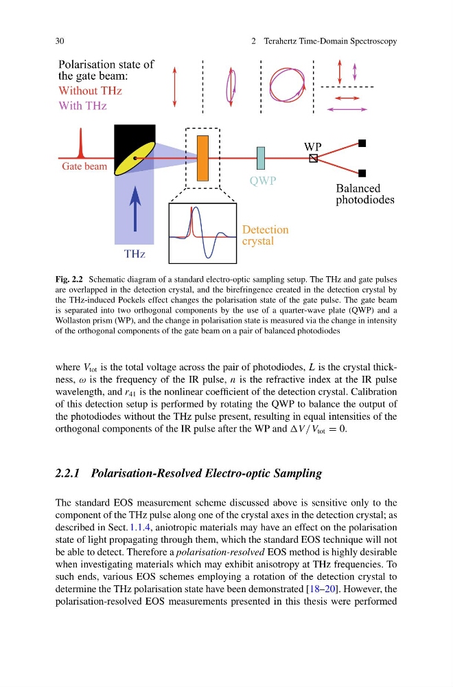
Fig. 2.2 Schematic diagram of a standard electro-optic sampling setup. The THz and gate pulses
are overlapped in the detection crystal, and the birefringence created in the detection crystal by
the THz-induced Pockels effect changes the polarisation state of the gate pulse. The gate beam
is separated into two orthogonal components by the use of a quarter-wave plate (QWP) and a
Wollaston prism (WP), and the change in polarisation state is measured via the change in intensity
of the orthogonal components of the gate beam on a pair of balanced photodiodes
where V tot is the total voltage across the pair of photodiodes, L is the crystal thickness, ω is the frequency of the IR pulse, n is the refractive index at the IR pulse
wavelength, and r 41 is the nonlinear coefficient of the detection crystal. Calibration
of this detection setup is performed by rotating the QWP to balance the output of
the photodiodes without the THz pulse present, resulting in equal intensities of the
orthogonal components of the IR pulse after the WP and /V tot = 0.
2.2.1 Polarisation-Resolved Electro-optic Sampling
The standard EOS measurement scheme discussed above is sensitive only to the
component of the THz pulse along one of the crystal axes in the detection crystal; as
described in Sect. 1.1.4, aniotropic materials may have an effect on the polarisation
state of light propagating through them, which the standard EOS technique will not
be able to detect. Therefore a polarisation-resolved EOS method is highly desirable
when investigating materials which may exhibit anisotropy at THz frequencies. To
such ends, various EOS schemes employing a rotation of the detection crystal to
determine the THz polarisation state have been demonstrated [18–20]. However, the
polarisation-resolved EOS measurements presented in this thesis were performed
2 Terahertz Time-Domain Spectroscopy
Fig. 2.2 Schematic diagram of a standard electro-optic sampling setup. The THz and gate pulses
are overlapped in the detection crystal, and the birefringence created in the detection crystal by
the THz-induced Pockels effect changes the polarisation state of the gate pulse. The gate beam
is separated into two orthogonal components by the use of a quarter-wave plate (QWP) and a
Wollaston prism (WP), and the change in polarisation state is measured via the change in intensity
of the orthogonal components of the gate beam on a pair of balanced photodiodes
where V tot is the total voltage across the pair of photodiodes, L is the crystal thickness, ω is the frequency of the IR pulse, n is the refractive index at the IR pulse
wavelength, and r 41 is the nonlinear coefficient of the detection crystal. Calibration
of this detection setup is performed by rotating the QWP to balance the output of
the photodiodes without the THz pulse present, resulting in equal intensities of the
orthogonal components of the IR pulse after the WP and /V tot = 0.
2.2.1 Polarisation-Resolved Electro-optic Sampling
The standard EOS measurement scheme discussed above is sensitive only to the
component of the THz pulse along one of the crystal axes in the detection crystal; as
described in Sect. 1.1.4, aniotropic materials may have an effect on the polarisation
state of light propagating through them, which the standard EOS technique will not
be able to detect. Therefore a polarisation-resolved EOS method is highly desirable
when investigating materials which may exhibit anisotropy at THz frequencies. To
such ends, various EOS schemes employing a rotation of the detection crystal to
determine the THz polarisation state have been demonstrated [18–20]. However, the
polarisation-resolved EOS measurements presented in this thesis were performed