

5.2 High-Field Terahertz Time-Domain Spectrometer
99
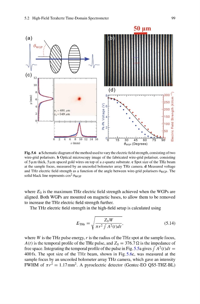
Fig. 5.6 a Schematic diagram of the method used to vary the electric field strength, consisting of two
wire-grid polarisers. b Optical microscopy image of the fabricated wire-grid polariser, consisting
of 5 µm thick, 5µm spaced gold wires on top of a z-quartz substrate. c Spot size of the THz beam
at the sample focus, measured by an uncooled bolometer array THz camera. d Measured voltage
and THz electric field strength as a function of the angle between wire-grid polarisers θ WGP . The
solid black line represents cos 2 θ WGP
where E 0 is the maximum THz electric field strength achieved when the WGPs are
aligned. Both WGPs are mounted on magnetic bases, to allow them to be removed
to increase the THz electric field strength further.
The THz electric field strength in the high-field setup is calculated using
E THz =
Z 0 W
πr 2
A 2 (t)dt
,
(5.14)
where W is the THz pulse energy, r is the radius of the THz spot at the sample focus,
A(t) is the temporal profile of the THz pulse, and Z 0 = 376.7 is the impedance of
free space. Integrating the temporal profile of the pulse in Fig. 5.5a gives
A
2
(t)dt =
400 fs. The spot size of the THz beam, shown in Fig. 5.6c, was measured at the
sample focus by an uncooled bolometer array THz camera, which gave an intensity
FWHM of πr
2
= 1.17 mm
2 . A pyroelectric detector (Gentec-EO QS5-THZ-BL)
99
Fig. 5.6 a Schematic diagram of the method used to vary the electric field strength, consisting of two
wire-grid polarisers. b Optical microscopy image of the fabricated wire-grid polariser, consisting
of 5 µm thick, 5µm spaced gold wires on top of a z-quartz substrate. c Spot size of the THz beam
at the sample focus, measured by an uncooled bolometer array THz camera. d Measured voltage
and THz electric field strength as a function of the angle between wire-grid polarisers θ WGP . The
solid black line represents cos 2 θ WGP
where E 0 is the maximum THz electric field strength achieved when the WGPs are
aligned. Both WGPs are mounted on magnetic bases, to allow them to be removed
to increase the THz electric field strength further.
The THz electric field strength in the high-field setup is calculated using
E THz =
Z 0 W
πr 2
A 2 (t)dt
,
(5.14)
where W is the THz pulse energy, r is the radius of the THz spot at the sample focus,
A(t) is the temporal profile of the THz pulse, and Z 0 = 376.7 is the impedance of
free space. Integrating the temporal profile of the pulse in Fig. 5.5a gives
A
2
(t)dt =
400 fs. The spot size of the THz beam, shown in Fig. 5.6c, was measured at the
sample focus by an uncooled bolometer array THz camera, which gave an intensity
FWHM of πr
2
= 1.17 mm
2 . A pyroelectric detector (Gentec-EO QS5-THZ-BL)