

5.2 High-Field Terahertz Time-Domain Spectrometer
97
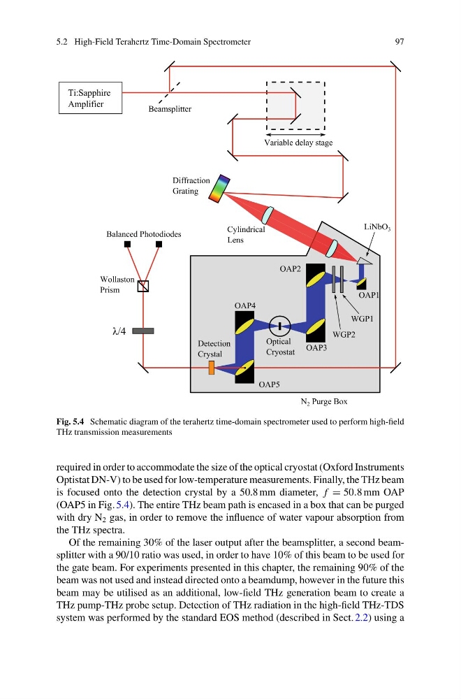
Fig. 5.4 Schematic diagram of the terahertz time-domain spectrometer used to perform high-field
THz transmission measurements
required in order to accommodate the size of the optical cryostat (Oxford Instruments
Optistat DN-V) to be used for low-temperature measurements. Finally, the THz beam
is focused onto the detection crystal by a 50.8 mm diameter, f = 50.8 mm OAP
(OAP5 in Fig. 5.4). The entire THz beam path is encased in a box that can be purged
with dry N 2 gas, in order to remove the influence of water vapour absorption from
the THz spectra.
Of the remaining 30% of the laser output after the beamsplitter, a second beamsplitter with a 90/10 ratio was used, in order to have 10% of this beam to be used for
the gate beam. For experiments presented in this chapter, the remaining 90% of the
beam was not used and instead directed onto a beamdump, however in the future this
beam may be utilised as an additional, low-field THz generation beam to create a
THz pump-THz probe setup. Detection of THz radiation in the high-field THz-TDS
system was performed by the standard EOS method (described in Sect. 2.2) using a
97
Fig. 5.4 Schematic diagram of the terahertz time-domain spectrometer used to perform high-field
THz transmission measurements
required in order to accommodate the size of the optical cryostat (Oxford Instruments
Optistat DN-V) to be used for low-temperature measurements. Finally, the THz beam
is focused onto the detection crystal by a 50.8 mm diameter, f = 50.8 mm OAP
(OAP5 in Fig. 5.4). The entire THz beam path is encased in a box that can be purged
with dry N 2 gas, in order to remove the influence of water vapour absorption from
the THz spectra.
Of the remaining 30% of the laser output after the beamsplitter, a second beamsplitter with a 90/10 ratio was used, in order to have 10% of this beam to be used for
the gate beam. For experiments presented in this chapter, the remaining 90% of the
beam was not used and instead directed onto a beamdump, however in the future this
beam may be utilised as an additional, low-field THz generation beam to create a
THz pump-THz probe setup. Detection of THz radiation in the high-field THz-TDS
system was performed by the standard EOS method (described in Sect. 2.2) using a