

2.4 Genealogy of Memristor Devices
59
2.4.1 Ideal Memristor
The ideal memristor has been defined in Chap. 1 and its properties are extensively
discussed in Sects. 2.1 and 2.2. For the sake of completeness of this section, here we
repeat the CR in the flux-charge domain of flux-controlled (resp., charge-controlled)
ideal memristor q = ˆ
q(ϕ) (resp., ϕ = ˆ
ϕ(q)). Hence, the corresponding statedependent Ohm’s law (DAE) in the voltage-current domain is:
• i = ˆ
q (ϕ)v and ˙
ϕ = v for a flux-controlled ideal memristor
• v = ˆ
ϕ (q)i and ˙
q = i for a charge-controlled ideal memristor.
No passive solid-state device with a memristive behavior was known when L. O.
Chua theoretically envisioned the existence of memristor [2]. To support the concept
of memristor, L. O. Chua proposed an ideal memristor emulator based on a two-port
network named mutator, as illustrated next.
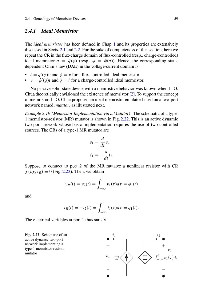
Example 2.19 (Memristor Implementation via a Mutator) The schematic of a type1 memristor-resistor (MR) mutator is shown in Fig. 2.22. This is an active dynamic
two-port network whose basic implementation requires the use of two controlled
sources. The CRs of a type-1 MR mutator are
v 1 =
d
dt
v 2
i 1 = −
d
dt
i 2 .
Suppose to connect to port 2 of the MR mutator a nonlinear resistor with CR
f (v R , i R ) = 0 (Fig. 2.23). Then, we obtain
v R (t) = v 2 (t) =
t
−∞
v 1 (τ )dτ = ϕ 1 (t)
and
i R (t) = −i 2 (t) =
t
−∞
i 1 (τ )dτ = q 1 (t).
The electrical variables at port 1 thus satisfy
Fig. 2.22 Schematic of an
active dynamic two-port
network implementing a
type-1 memristor-resistor
mutator
59
2.4.1 Ideal Memristor
The ideal memristor has been defined in Chap. 1 and its properties are extensively
discussed in Sects. 2.1 and 2.2. For the sake of completeness of this section, here we
repeat the CR in the flux-charge domain of flux-controlled (resp., charge-controlled)
ideal memristor q = ˆ
q(ϕ) (resp., ϕ = ˆ
ϕ(q)). Hence, the corresponding statedependent Ohm’s law (DAE) in the voltage-current domain is:
• i = ˆ
q (ϕ)v and ˙
ϕ = v for a flux-controlled ideal memristor
• v = ˆ
ϕ (q)i and ˙
q = i for a charge-controlled ideal memristor.
No passive solid-state device with a memristive behavior was known when L. O.
Chua theoretically envisioned the existence of memristor [2]. To support the concept
of memristor, L. O. Chua proposed an ideal memristor emulator based on a two-port
network named mutator, as illustrated next.
Example 2.19 (Memristor Implementation via a Mutator) The schematic of a type1 memristor-resistor (MR) mutator is shown in Fig. 2.22. This is an active dynamic
two-port network whose basic implementation requires the use of two controlled
sources. The CRs of a type-1 MR mutator are
v 1 =
d
dt
v 2
i 1 = −
d
dt
i 2 .
Suppose to connect to port 2 of the MR mutator a nonlinear resistor with CR
f (v R , i R ) = 0 (Fig. 2.23). Then, we obtain
v R (t) = v 2 (t) =
t
−∞
v 1 (τ )dτ = ϕ 1 (t)
and
i R (t) = −i 2 (t) =
t
−∞
i 1 (τ )dτ = q 1 (t).
The electrical variables at port 1 thus satisfy
Fig. 2.22 Schematic of an
active dynamic two-port
network implementing a
type-1 memristor-resistor
mutator