

422
11 Nonlinear Dynamics of Circuits with Mem-Elements
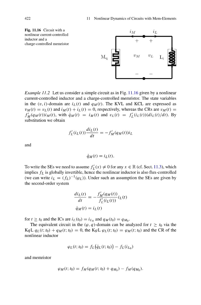
Fig. 11.16 Circuit with a
nonlinear current-controlled
inductor and a
charge-controlled memristor
M q
L i
−
+
−
+
v L
v M
i M
i L
Example 11.2 Let us consider a simple circuit as in Fig. 11.16 given by a nonlinear
current-controlled inductor and a charge-controlled memristor. The state variables
in the (v, i)-domain are i L (t) and q M (t). The KVL and KCL are expressed as
v M (t) = v L (t) and i M (t) + i L (t) = 0, respectively, whereas the CRs are v M (t) =
f
M (q M (t))i M (t), with ˙
q M (t) = i M (t) and v L (t) = f
L (i L (t))(di L (t)/dt). By
substitution we obtain
f
L (i L (t))
di L (t)
dt
= −f
M (q M (t))i L
and
˙
q M (t) = i L (t).
To write the SEs we need to assume f
L (x) = 0 for any x ∈ R (cf. Sect. 11.3), which
implies f L is globally invertible, hence the nonlinear inductor is also flux-controlled
(we can write i L = (f L ) −1 (ϕ L )). Under such an assumption the SEs are given by
the second-order system
di L (t)
dt
= −
f
M (q M (t))
f
L (i L (t))
i L (t)
˙
q M (t) = i L (t)
for t ≥ t 0 and the ICs are i L (t 0 ) = i L 0 and q M (t 0 ) = q M 0 .
The equivalent circuit in the (ϕ, q)-domain can be analyzed for t ≥ t 0 via the
KqL q L (t; t 0 ) + q M (t; t 0 ) = 0, the KϕL ϕ L (t; t 0 ) = ϕ M (t; t 0 ) and the CR of the
nonlinear inductor
ϕ L (t; t 0 ) = f L
˙
q L (t; t 0 )
− f L (i L 0 )
and memristor
ϕ M (t; t 0 ) = f M (q M (t; t 0 ) + q M 0 ) − f M (q M 0 ).
11 Nonlinear Dynamics of Circuits with Mem-Elements
Fig. 11.16 Circuit with a
nonlinear current-controlled
inductor and a
charge-controlled memristor
M q
L i
−
+
−
+
v L
v M
i M
i L
Example 11.2 Let us consider a simple circuit as in Fig. 11.16 given by a nonlinear
current-controlled inductor and a charge-controlled memristor. The state variables
in the (v, i)-domain are i L (t) and q M (t). The KVL and KCL are expressed as
v M (t) = v L (t) and i M (t) + i L (t) = 0, respectively, whereas the CRs are v M (t) =
f
M (q M (t))i M (t), with ˙
q M (t) = i M (t) and v L (t) = f
L (i L (t))(di L (t)/dt). By
substitution we obtain
f
L (i L (t))
di L (t)
dt
= −f
M (q M (t))i L
and
˙
q M (t) = i L (t).
To write the SEs we need to assume f
L (x) = 0 for any x ∈ R (cf. Sect. 11.3), which
implies f L is globally invertible, hence the nonlinear inductor is also flux-controlled
(we can write i L = (f L ) −1 (ϕ L )). Under such an assumption the SEs are given by
the second-order system
di L (t)
dt
= −
f
M (q M (t))
f
L (i L (t))
i L (t)
˙
q M (t) = i L (t)
for t ≥ t 0 and the ICs are i L (t 0 ) = i L 0 and q M (t 0 ) = q M 0 .
The equivalent circuit in the (ϕ, q)-domain can be analyzed for t ≥ t 0 via the
KqL q L (t; t 0 ) + q M (t; t 0 ) = 0, the KϕL ϕ L (t; t 0 ) = ϕ M (t; t 0 ) and the CR of the
nonlinear inductor
ϕ L (t; t 0 ) = f L
˙
q L (t; t 0 )
− f L (i L 0 )
and memristor
ϕ M (t; t 0 ) = f M (q M (t; t 0 ) + q M 0 ) − f M (q M 0 ).