

11.6 Chaotic Circuit with Memcapacitor and Memristor
419
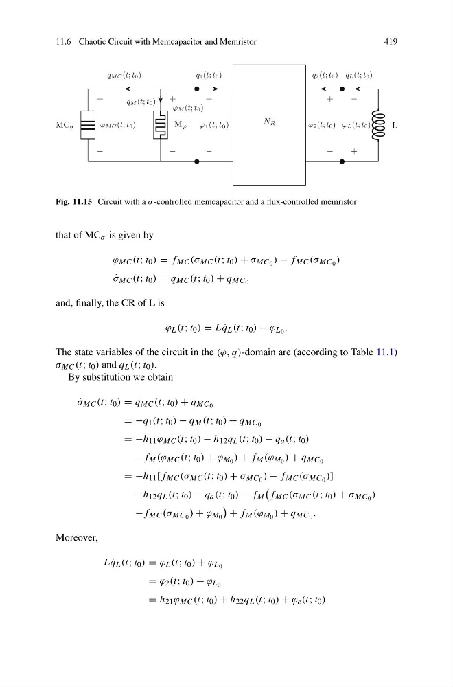
Fig. 11.15 Circuit with a σ -controlled memcapacitor and a flux-controlled memristor
that of MC σ is given by
ϕ MC (t; t 0 ) = f MC (σ MC (t; t 0 ) + σ MC 0 ) − f MC (σ MC 0 )
˙
σ MC (t; t 0 ) = q MC (t; t 0 ) + q MC 0
and, finally, the CR of L is
ϕ L (t; t 0 ) = L ˙
q L (t; t 0 ) − ϕ L 0 .
The state variables of the circuit in the (ϕ, q)-domain are (according to Table 11.1)
σ MC (t; t 0 ) and q L (t; t 0 ).
By substitution we obtain
˙
σ MC (t; t 0 ) = q MC (t; t 0 ) + q MC 0
= −q 1 (t; t 0 ) − q M (t; t 0 ) + q MC 0
= −h 11 ϕ MC (t; t 0 ) − h 12 q L (t; t 0 ) − q a (t; t 0 )
−f M (ϕ MC (t; t 0 ) + ϕ M 0 ) + f M (ϕ M 0 ) + q MC 0
= −h 11 [f MC (σ MC (t; t 0 ) + σ MC 0 ) − f MC (σ MC 0 )]
−h 12 q L (t; t 0 ) − q a (t; t 0 ) − f M
f MC (σ MC (t; t 0 ) + σ MC 0 )
−f MC (σ MC 0 ) + ϕ M 0
+ f M (ϕ M 0 ) + q MC 0 .
Moreover,
L ˙
q L (t; t 0 ) = ϕ L (t; t 0 ) + ϕ L 0
= ϕ 2 (t; t 0 ) + ϕ L 0
= h 21 ϕ MC (t; t 0 ) + h 22 q L (t; t 0 ) + ϕ e (t; t 0 )
419
Fig. 11.15 Circuit with a σ -controlled memcapacitor and a flux-controlled memristor
that of MC σ is given by
ϕ MC (t; t 0 ) = f MC (σ MC (t; t 0 ) + σ MC 0 ) − f MC (σ MC 0 )
˙
σ MC (t; t 0 ) = q MC (t; t 0 ) + q MC 0
and, finally, the CR of L is
ϕ L (t; t 0 ) = L ˙
q L (t; t 0 ) − ϕ L 0 .
The state variables of the circuit in the (ϕ, q)-domain are (according to Table 11.1)
σ MC (t; t 0 ) and q L (t; t 0 ).
By substitution we obtain
˙
σ MC (t; t 0 ) = q MC (t; t 0 ) + q MC 0
= −q 1 (t; t 0 ) − q M (t; t 0 ) + q MC 0
= −h 11 ϕ MC (t; t 0 ) − h 12 q L (t; t 0 ) − q a (t; t 0 )
−f M (ϕ MC (t; t 0 ) + ϕ M 0 ) + f M (ϕ M 0 ) + q MC 0
= −h 11 [f MC (σ MC (t; t 0 ) + σ MC 0 ) − f MC (σ MC 0 )]
−h 12 q L (t; t 0 ) − q a (t; t 0 ) − f M
f MC (σ MC (t; t 0 ) + σ MC 0 )
−f MC (σ MC 0 ) + ϕ M 0
+ f M (ϕ M 0 ) + q MC 0 .
Moreover,
L ˙
q L (t; t 0 ) = ϕ L (t; t 0 ) + ϕ L 0
= ϕ 2 (t; t 0 ) + ϕ L 0
= h 21 ϕ MC (t; t 0 ) + h 22 q L (t; t 0 ) + ϕ e (t; t 0 )