

11.6 Chaotic Circuit with Memcapacitor and Memristor
415
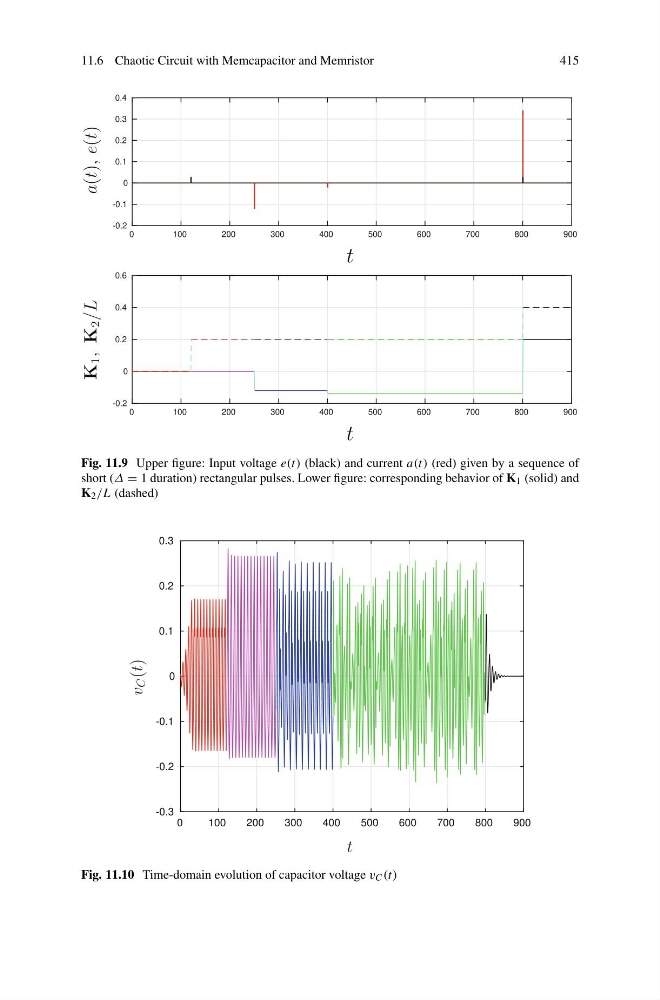
Fig. 11.9 Upper figure: Input voltage e(t) (black) and current a(t) (red) given by a sequence of
short (Δ = 1 duration) rectangular pulses. Lower figure: corresponding behavior of K 1 (solid) and
K 2 /L (dashed)
Fig. 11.10 Time-domain evolution of capacitor voltage v C (t)
415
Fig. 11.9 Upper figure: Input voltage e(t) (black) and current a(t) (red) given by a sequence of
short (Δ = 1 duration) rectangular pulses. Lower figure: corresponding behavior of K 1 (solid) and
K 2 /L (dashed)
Fig. 11.10 Time-domain evolution of capacitor voltage v C (t)