

11.3 Classes LME and LME of Nonlinear Circuits with Mem-Elements
397
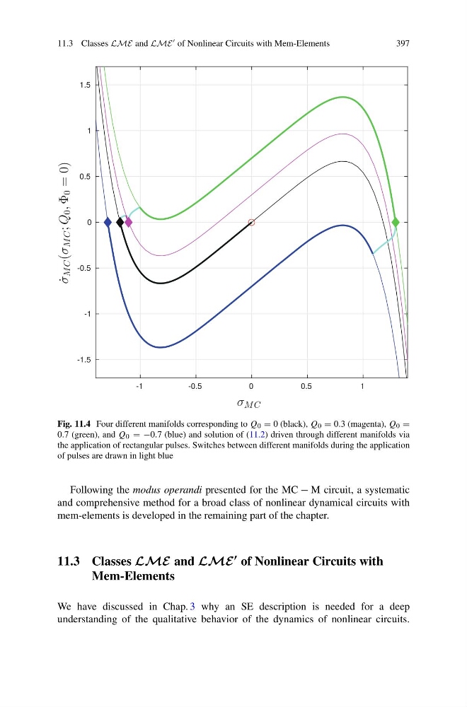
Fig. 11.4 Four different manifolds corresponding to Q 0 = 0 (black), Q 0 = 0.3 (magenta), Q 0 =
0.7 (green), and Q 0 = −0.7 (blue) and solution of (11.2) driven through different manifolds via
the application of rectangular pulses. Switches between different manifolds during the application
of pulses are drawn in light blue
Following the modus operandi presented for the MC − M circuit, a systematic
and comprehensive method for a broad class of nonlinear dynamical circuits with
mem-elements is developed in the remaining part of the chapter.
11.3 Classes LME and LME of Nonlinear Circuits with
Mem-Elements
We have discussed in Chap. 3 why an SE description is needed for a deep
understanding of the qualitative behavior of the dynamics of nonlinear circuits.
397
Fig. 11.4 Four different manifolds corresponding to Q 0 = 0 (black), Q 0 = 0.3 (magenta), Q 0 =
0.7 (green), and Q 0 = −0.7 (blue) and solution of (11.2) driven through different manifolds via
the application of rectangular pulses. Switches between different manifolds during the application
of pulses are drawn in light blue
Following the modus operandi presented for the MC − M circuit, a systematic
and comprehensive method for a broad class of nonlinear dynamical circuits with
mem-elements is developed in the remaining part of the chapter.
11.3 Classes LME and LME of Nonlinear Circuits with
Mem-Elements
We have discussed in Chap. 3 why an SE description is needed for a deep
understanding of the qualitative behavior of the dynamics of nonlinear circuits.