

11.2 Motivating Example
391
ϕ(t; t 0 ) =
t
t 0
ϕ(τ )dτ ;
q(t; t 0 ) =
t
t 0
i(τ )dτ
at the terminals of any element D, where t ≥ t 0 . Kirchhoff charge laws (KqLs) are
expressed in the (ϕ, q)-domain as Aq(t; t 0 ) = 0 while Kirchhoff flux laws (KϕLs)
read as Bϕ(t; t 0 ) = 0 for t ≥ t 0 . We denoted by q(t; t 0 ) and ϕ(t; t 0 ) the vectors of
incremental charges and fluxes of the elements, whereas A and B are the reduced
incidence matrix and fundamental loop matrix, respectively (Chap. 3).
Since KqLs and KϕLs are written in incremental form, the CR of each element D
has to be expressed as a link between the incremental flux and charge at its terminals.
For instance, using the passive convention, a σ -controlled memcapacitor is defined
by ϕ MC (t) = f MC (σ MC (t)). In the (ϕ, q)-domain the CRs for t ≥ t 0 are (see
Sect. 11.4 for more details)
ϕ MC (t; t 0 ) = f MC (σ MC (t; t 0 ) + σ MC 0 ) − f MC (σ MC 0 )
q MC (t; t 0 ) = ˙
σ MC (t; t 0 ) − q MC (t 0 ).
For pedagogical reasons, we find it useful to first highlight key features and
advantages of the analysis in the flux-charge domain by means of a simple circuit
in N e (Sect. 11.2). Then, we extend FCAM and develop a systematic approach for
a comprehensive analysis of circuits in N e in the (ϕ, q)-domain in the subsequent
Sects. 11.3–11.5.
11.2 Motivating Example
11.2.1 Reduction of Order
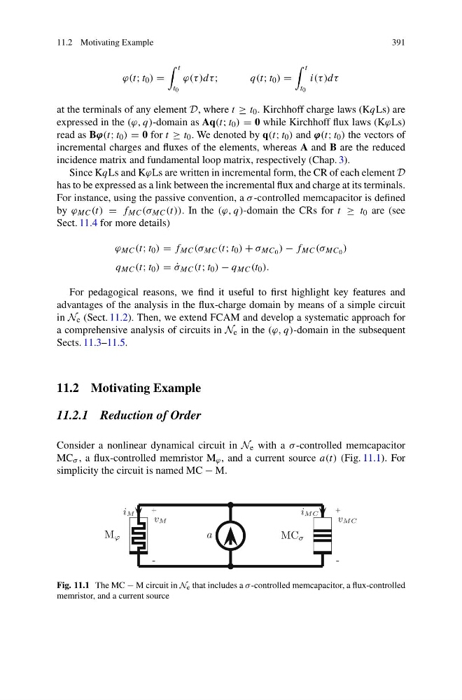
Consider a nonlinear dynamical circuit in N e with a σ -controlled memcapacitor
MC σ , a flux-controlled memristor M ϕ , and a current source a(t) (Fig. 11.1). For
simplicity the circuit is named MC − M.
M ϕ
+
-
vM
iM
a
MC σ
+
-
vMC
iMC
Fig. 11.1 The MC − M circuit in N e that includes a σ -controlled memcapacitor, a flux-controlled
memristor, and a current source
391
ϕ(t; t 0 ) =
t
t 0
ϕ(τ )dτ ;
q(t; t 0 ) =
t
t 0
i(τ )dτ
at the terminals of any element D, where t ≥ t 0 . Kirchhoff charge laws (KqLs) are
expressed in the (ϕ, q)-domain as Aq(t; t 0 ) = 0 while Kirchhoff flux laws (KϕLs)
read as Bϕ(t; t 0 ) = 0 for t ≥ t 0 . We denoted by q(t; t 0 ) and ϕ(t; t 0 ) the vectors of
incremental charges and fluxes of the elements, whereas A and B are the reduced
incidence matrix and fundamental loop matrix, respectively (Chap. 3).
Since KqLs and KϕLs are written in incremental form, the CR of each element D
has to be expressed as a link between the incremental flux and charge at its terminals.
For instance, using the passive convention, a σ -controlled memcapacitor is defined
by ϕ MC (t) = f MC (σ MC (t)). In the (ϕ, q)-domain the CRs for t ≥ t 0 are (see
Sect. 11.4 for more details)
ϕ MC (t; t 0 ) = f MC (σ MC (t; t 0 ) + σ MC 0 ) − f MC (σ MC 0 )
q MC (t; t 0 ) = ˙
σ MC (t; t 0 ) − q MC (t 0 ).
For pedagogical reasons, we find it useful to first highlight key features and
advantages of the analysis in the flux-charge domain by means of a simple circuit
in N e (Sect. 11.2). Then, we extend FCAM and develop a systematic approach for
a comprehensive analysis of circuits in N e in the (ϕ, q)-domain in the subsequent
Sects. 11.3–11.5.
11.2 Motivating Example
11.2.1 Reduction of Order
Consider a nonlinear dynamical circuit in N e with a σ -controlled memcapacitor
MC σ , a flux-controlled memristor M ϕ , and a current source a(t) (Fig. 11.1). For
simplicity the circuit is named MC − M.
M ϕ
+
-
vM
iM
a
MC σ
+
-
vMC
iMC
Fig. 11.1 The MC − M circuit in N e that includes a σ -controlled memcapacitor, a flux-controlled
memristor, and a current source