

10
1 Device Modeling and Circuit Elements
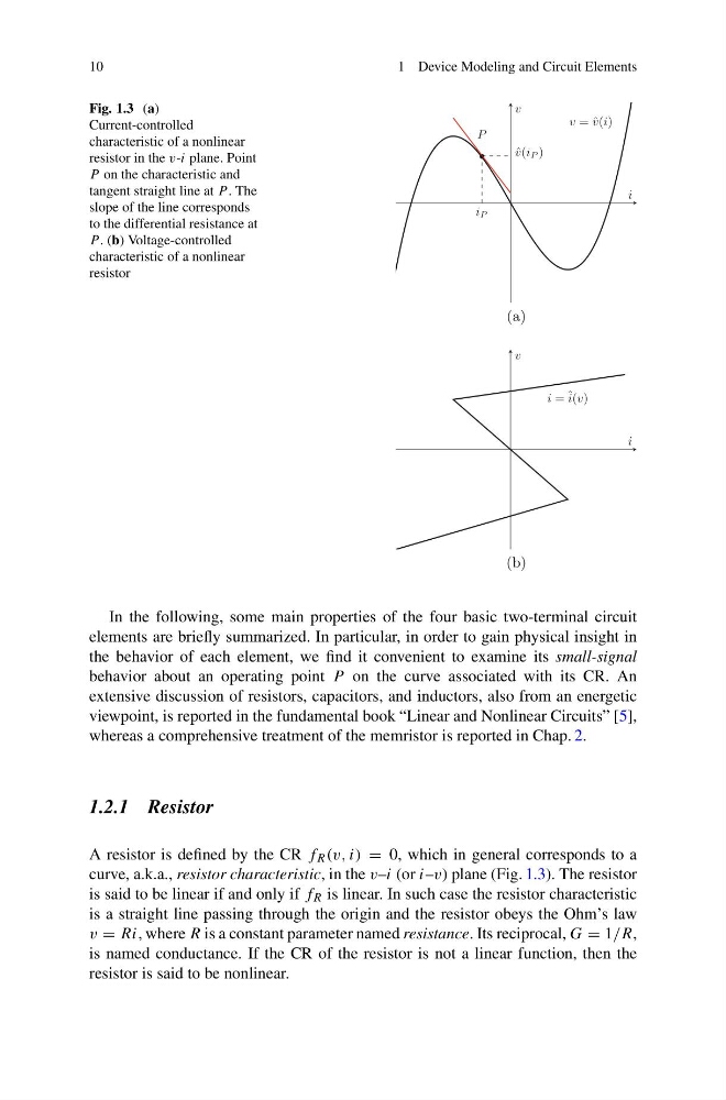
Fig. 1.3 (a)
Current-controlled
characteristic of a nonlinear
resistor in the v-i plane. Point
P on the characteristic and
tangent straight line at P . The
slope of the line corresponds
to the differential resistance at
P . (b) Voltage-controlled
characteristic of a nonlinear
resistor
v = ˆ
v(i)
•
P
i P
ˆ
v(i P )
i
v
(a)
i = ˆ i(v)
i
v
(b)
In the following, some main properties of the four basic two-terminal circuit
elements are briefly summarized. In particular, in order to gain physical insight in
the behavior of each element, we find it convenient to examine its small-signal
behavior about an operating point P on the curve associated with its CR. An
extensive discussion of resistors, capacitors, and inductors, also from an energetic
viewpoint, is reported in the fundamental book “Linear and Nonlinear Circuits” [5],
whereas a comprehensive treatment of the memristor is reported in Chap. 2.
1.2.1 Resistor
A resistor is defined by the CR f R (v, i) = 0, which in general corresponds to a
curve, a.k.a., resistor characteristic, in the v–i (or i–v) plane (Fig. 1.3). The resistor
is said to be linear if and only if f R is linear. In such case the resistor characteristic
is a straight line passing through the origin and the resistor obeys the Ohm’s law
v = Ri, where R is a constant parameter named resistance. Its reciprocal, G = 1/R,
is named conductance. If the CR of the resistor is not a linear function, then the
resistor is said to be nonlinear.
1 Device Modeling and Circuit Elements
Fig. 1.3 (a)
Current-controlled
characteristic of a nonlinear
resistor in the v-i plane. Point
P on the characteristic and
tangent straight line at P . The
slope of the line corresponds
to the differential resistance at
P . (b) Voltage-controlled
characteristic of a nonlinear
resistor
v = ˆ
v(i)
•
P
i P
ˆ
v(i P )
i
v
(a)
i = ˆ i(v)
i
v
(b)
In the following, some main properties of the four basic two-terminal circuit
elements are briefly summarized. In particular, in order to gain physical insight in
the behavior of each element, we find it convenient to examine its small-signal
behavior about an operating point P on the curve associated with its CR. An
extensive discussion of resistors, capacitors, and inductors, also from an energetic
viewpoint, is reported in the fundamental book “Linear and Nonlinear Circuits” [5],
whereas a comprehensive treatment of the memristor is reported in Chap. 2.
1.2.1 Resistor
A resistor is defined by the CR f R (v, i) = 0, which in general corresponds to a
curve, a.k.a., resistor characteristic, in the v–i (or i–v) plane (Fig. 1.3). The resistor
is said to be linear if and only if f R is linear. In such case the resistor characteristic
is a straight line passing through the origin and the resistor obeys the Ohm’s law
v = Ri, where R is a constant parameter named resistance. Its reciprocal, G = 1/R,
is named conductance. If the CR of the resistor is not a linear function, then the
resistor is said to be nonlinear.