

1.2 Four Basic Two-Terminal Circuit Elements
9
Summing up, the above axiomatic approach allows to give a systematic definition
of the four basic circuit elements.
Definition 1.1 (Resistor, Capacitor, Inductor, and Memristor) A two-terminal
circuit element is called resistor, capacitor, inductor, and memristor if and only if its
CR can be expressed by an algebraic relationship involving only the variable pairs
(v, i), (ϕ, i), (q, v), and (ϕ, q), respectively. In particular, the CR
• f R (v, i) = 0 defines a resistor
• f C (q, v) = 0 defines a capacitor
• f L (ϕ, i) = 0 defines an inductor
• f M (ϕ, q) = 0 defines a memristor.
Recall that an algebraic relation is any equation involving strictly algebraic
operations only. In particular, no differentiation, integration, or time delay operation
may be involved.
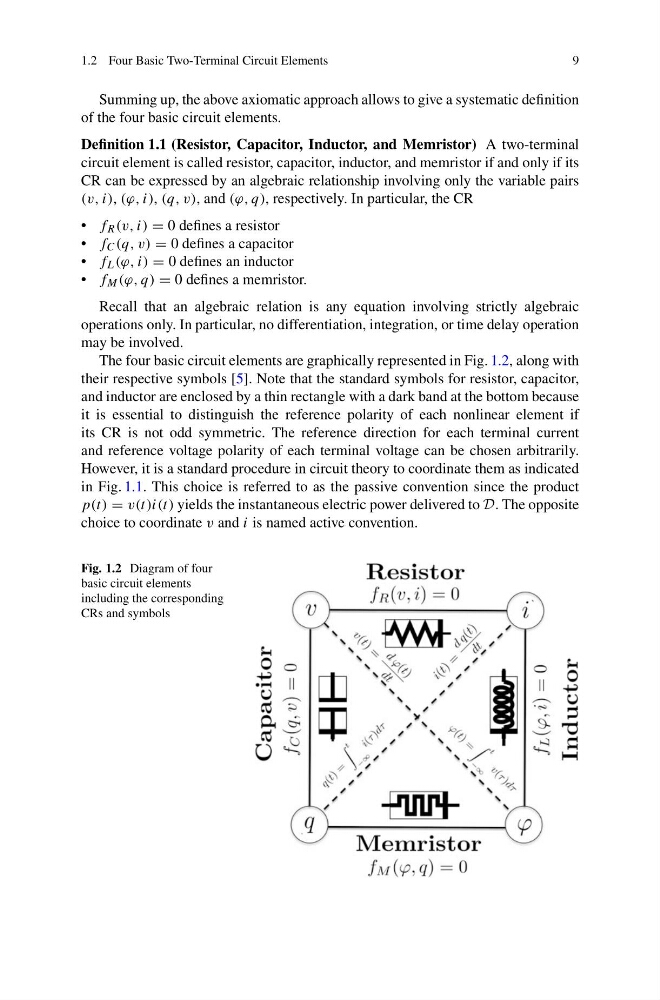
The four basic circuit elements are graphically represented in Fig. 1.2, along with
their respective symbols [5]. Note that the standard symbols for resistor, capacitor,
and inductor are enclosed by a thin rectangle with a dark band at the bottom because
it is essential to distinguish the reference polarity of each nonlinear element if
its CR is not odd symmetric. The reference direction for each terminal current
and reference voltage polarity of each terminal voltage can be chosen arbitrarily.
However, it is a standard procedure in circuit theory to coordinate them as indicated
in Fig. 1.1. This choice is referred to as the passive convention since the product
p(t) = v(t)i(t) yields the instantaneous electric power delivered to D. The opposite
choice to coordinate v and i is named active convention.
Fig. 1.2 Diagram of four
basic circuit elements
including the corresponding
CRs and symbols
9
Summing up, the above axiomatic approach allows to give a systematic definition
of the four basic circuit elements.
Definition 1.1 (Resistor, Capacitor, Inductor, and Memristor) A two-terminal
circuit element is called resistor, capacitor, inductor, and memristor if and only if its
CR can be expressed by an algebraic relationship involving only the variable pairs
(v, i), (ϕ, i), (q, v), and (ϕ, q), respectively. In particular, the CR
• f R (v, i) = 0 defines a resistor
• f C (q, v) = 0 defines a capacitor
• f L (ϕ, i) = 0 defines an inductor
• f M (ϕ, q) = 0 defines a memristor.
Recall that an algebraic relation is any equation involving strictly algebraic
operations only. In particular, no differentiation, integration, or time delay operation
may be involved.
The four basic circuit elements are graphically represented in Fig. 1.2, along with
their respective symbols [5]. Note that the standard symbols for resistor, capacitor,
and inductor are enclosed by a thin rectangle with a dark band at the bottom because
it is essential to distinguish the reference polarity of each nonlinear element if
its CR is not odd symmetric. The reference direction for each terminal current
and reference voltage polarity of each terminal voltage can be chosen arbitrarily.
However, it is a standard procedure in circuit theory to coordinate them as indicated
in Fig. 1.1. This choice is referred to as the passive convention since the product
p(t) = v(t)i(t) yields the instantaneous electric power delivered to D. The opposite
choice to coordinate v and i is named active convention.
Fig. 1.2 Diagram of four
basic circuit elements
including the corresponding
CRs and symbols