

Appendix 1: Nonsingularity of H 22
313
autonomous case, each manifold is positively invariant. Different regimes, reducedorder dynamics, and attractors therefore coexist in a memristor circuit for a fixed
set of parameters and nonlinearities. The chief results in the chapter concern the
nonautonomous case where time-varying independent sources are present. In such
a case, general explicit formulas are obtained for effectively designing impulsive
sources with finite time-duration in order to programme the different regimes and
nonlinear dynamics that can be displayed by the memristor circuits, i.e., to drive
at one will solutions between different manifolds, reduced-order dynamics and
attractors. This gives a sound theoretical foundation to a common practice for
changing the dynamics in memristor circuits that has been so far mainly based on
experimental trials and/or heuristic means.
Appendix 1: Nonsingularity of H 22
We provide some brief considerations about assumption (A4). Consider for simplicity a network N satisfying (A1)–(A3) with only one flux-controlled memristor M
in parallel to C 1 . Also suppose that N has only positive resistors, i.e., γ G = λ R =
ρ G = ρ R = 0. In this case, we can show that (A4) is satisfied, i.e., det H 22 = 0, if
and only if the next topological assumption holds.
(A5) The network N has no cut-sets made of capacitors C 2 , . . . , C n C and/or charge
sources and no loops made of M, inductors L 1 , . . . , L n L and/or flux sources.
The proof follows by an argument for testing the nonsingularity of the hybrid
representation of N R as in Corollary 3 in [13]. 8 Furthermore, if (A4) fails, then
the state space in the (v, i)-domain can be foliated in ∞ 1 planar manifolds, as
illustrated in the next example.
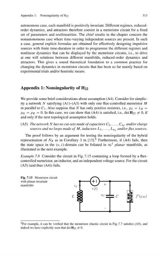
Example 7.8 Consider the circuit in Fig. 7.15 containing a loop formed by a fluxcontrolled memristor, an inductor, and an independent voltage source. For the circuit
(A5) (and thus (A4)) fails.
Fig. 7.15 Memristor circuit
with planar invariant
manifolds
L
e(t)
C
f (ϕ M )
i L
−
+
v C
8 For example, it can be verified that the memristor chaotic circuit in Fig. 7.7 satisfies (A5), and
indeed we have explicitly seen that det H 22 = 0.
313
autonomous case, each manifold is positively invariant. Different regimes, reducedorder dynamics, and attractors therefore coexist in a memristor circuit for a fixed
set of parameters and nonlinearities. The chief results in the chapter concern the
nonautonomous case where time-varying independent sources are present. In such
a case, general explicit formulas are obtained for effectively designing impulsive
sources with finite time-duration in order to programme the different regimes and
nonlinear dynamics that can be displayed by the memristor circuits, i.e., to drive
at one will solutions between different manifolds, reduced-order dynamics and
attractors. This gives a sound theoretical foundation to a common practice for
changing the dynamics in memristor circuits that has been so far mainly based on
experimental trials and/or heuristic means.
Appendix 1: Nonsingularity of H 22
We provide some brief considerations about assumption (A4). Consider for simplicity a network N satisfying (A1)–(A3) with only one flux-controlled memristor M
in parallel to C 1 . Also suppose that N has only positive resistors, i.e., γ G = λ R =
ρ G = ρ R = 0. In this case, we can show that (A4) is satisfied, i.e., det H 22 = 0, if
and only if the next topological assumption holds.
(A5) The network N has no cut-sets made of capacitors C 2 , . . . , C n C and/or charge
sources and no loops made of M, inductors L 1 , . . . , L n L and/or flux sources.
The proof follows by an argument for testing the nonsingularity of the hybrid
representation of N R as in Corollary 3 in [13]. 8 Furthermore, if (A4) fails, then
the state space in the (v, i)-domain can be foliated in ∞ 1 planar manifolds, as
illustrated in the next example.
Example 7.8 Consider the circuit in Fig. 7.15 containing a loop formed by a fluxcontrolled memristor, an inductor, and an independent voltage source. For the circuit
(A5) (and thus (A4)) fails.
Fig. 7.15 Memristor circuit
with planar invariant
manifolds
L
e(t)
C
f (ϕ M )
i L
−
+
v C
8 For example, it can be verified that the memristor chaotic circuit in Fig. 7.7 satisfies (A5), and
indeed we have explicitly seen that det H 22 = 0.