

7.4 State Equations in the Flux-Charge Domain
285
C
L
R
h (q M )
+
−
v 1
i1
+
−
vC
iC
+
−
+
−
v2
i2
vL
iL
−
+
R
+
−
ϕ C (t; t 0 )
qC(t; t0)
(a)
(b)
−
+
ϕM (t; t0)
ϕL(t; t0)
qL(t; t0)
−
+
q M (t; t 0 )
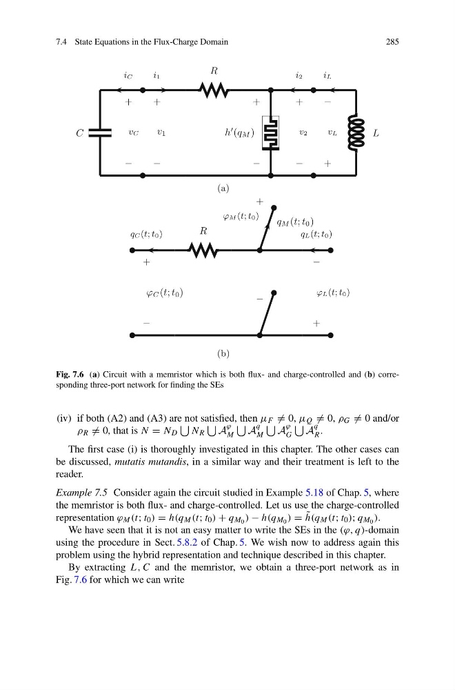
Fig. 7.6 (a) Circuit with a memristor which is both flux- and charge-controlled and (b) corresponding three-port network for finding the SEs
(iv) if both (A2) and (A3) are not satisfied, then μ F = 0, μ Q = 0, ρ G = 0 and/or
ρ R = 0, that is N = N D
N R
A
ϕ
M
A
q
M
A
ϕ
G
A
q
R .
The first case (i) is thoroughly investigated in this chapter. The other cases can
be discussed, mutatis mutandis, in a similar way and their treatment is left to the
reader.
Example 7.5 Consider again the circuit studied in Example 5.18 of Chap. 5, where
the memristor is both flux- and charge-controlled. Let us use the charge-controlled
representation ϕ M (t; t 0 ) = h(q M (t; t 0 ) + q M 0 ) − h(q M 0 ) = ˜
h(q M (t; t 0 ); q M 0 ).
We have seen that it is not an easy matter to write the SEs in the (ϕ, q)-domain
using the procedure in Sect. 5.8.2 of Chap. 5. We wish now to address again this
problem using the hybrid representation and technique described in this chapter.
By extracting L, C and the memristor, we obtain a three-port network as in
Fig. 7.6 for which we can write
285
C
L
R
h (q M )
+
−
v 1
i1
+
−
vC
iC
+
−
+
−
v2
i2
vL
iL
−
+
R
+
−
ϕ C (t; t 0 )
qC(t; t0)
(a)
(b)
−
+
ϕM (t; t0)
ϕL(t; t0)
qL(t; t0)
−
+
q M (t; t 0 )
Fig. 7.6 (a) Circuit with a memristor which is both flux- and charge-controlled and (b) corresponding three-port network for finding the SEs
(iv) if both (A2) and (A3) are not satisfied, then μ F = 0, μ Q = 0, ρ G = 0 and/or
ρ R = 0, that is N = N D
N R
A
ϕ
M
A
q
M
A
ϕ
G
A
q
R .
The first case (i) is thoroughly investigated in this chapter. The other cases can
be discussed, mutatis mutandis, in a similar way and their treatment is left to the
reader.
Example 7.5 Consider again the circuit studied in Example 5.18 of Chap. 5, where
the memristor is both flux- and charge-controlled. Let us use the charge-controlled
representation ϕ M (t; t 0 ) = h(q M (t; t 0 ) + q M 0 ) − h(q M 0 ) = ˜
h(q M (t; t 0 ); q M 0 ).
We have seen that it is not an easy matter to write the SEs in the (ϕ, q)-domain
using the procedure in Sect. 5.8.2 of Chap. 5. We wish now to address again this
problem using the hybrid representation and technique described in this chapter.
By extracting L, C and the memristor, we obtain a three-port network as in
Fig. 7.6 for which we can write