

7.3 Structure of Memristor Network and Differential Algebraic Equation. . .
283
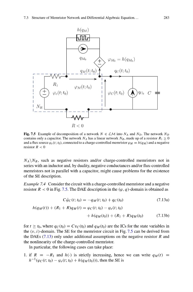
Fig. 7.5 Example of decomposition of a network N ∈ LM into N A and N D . The network N D
contains only a capacitor. The network N A has a linear network N R , made up of a resistor R 1 ≥ 0
and a flux source ϕ e (t; t 0 ), connected to a charge-controlled memristor ϕ M = h(q M ) and a negative
resistor R < 0
N A \N R , such as negative resistors and/or charge-controlled memristors not in
series with an inductor and, by duality, negative conductances and/or flux-controlled
memristors not in parallel with a capacitor, might cause problems for the existence
of the SE description.
Example 7.4 Consider the circuit with a charge-controlled memristor and a negative
resistor R < 0 in Fig. 7.5. The DAE description in the (ϕ, q)-domain is obtained as
C ˙
ϕ C (t; t 0 ) = −q M (t; t 0 ) + q C (t 0 )
(7.13a)
h(q M (t)) + (R 1 + R)q M (t) = ϕ C (t; t 0 ) − ϕ e (t; t 0 )
+ h(q M (t 0 )) + (R 1 + R)q M (t 0 )
(7.13b)
for t ≥ t 0 , where q C (t 0 ) = Cv C (t 0 ) and q M (t 0 ) are the ICs for the state variables in
the (v, i)-domain. The SE for the memristor circuit in Fig. 7.5 can be derived from
the DAEs (7.13) only under additional assumptions on the negative resistor R and
the nonlinearity of the charge-controlled memristor.
In particular, the following cases can take place:
1. if R = −R 1 and h(·) is strictly increasing, hence we can write q M (t) =
h −1 (ϕ C (t; t 0 ) − ϕ e (t; t 0 ) + h(q M (t 0 ))), then the SE is
283
Fig. 7.5 Example of decomposition of a network N ∈ LM into N A and N D . The network N D
contains only a capacitor. The network N A has a linear network N R , made up of a resistor R 1 ≥ 0
and a flux source ϕ e (t; t 0 ), connected to a charge-controlled memristor ϕ M = h(q M ) and a negative
resistor R < 0
N A \N R , such as negative resistors and/or charge-controlled memristors not in
series with an inductor and, by duality, negative conductances and/or flux-controlled
memristors not in parallel with a capacitor, might cause problems for the existence
of the SE description.
Example 7.4 Consider the circuit with a charge-controlled memristor and a negative
resistor R < 0 in Fig. 7.5. The DAE description in the (ϕ, q)-domain is obtained as
C ˙
ϕ C (t; t 0 ) = −q M (t; t 0 ) + q C (t 0 )
(7.13a)
h(q M (t)) + (R 1 + R)q M (t) = ϕ C (t; t 0 ) − ϕ e (t; t 0 )
+ h(q M (t 0 )) + (R 1 + R)q M (t 0 )
(7.13b)
for t ≥ t 0 , where q C (t 0 ) = Cv C (t 0 ) and q M (t 0 ) are the ICs for the state variables in
the (v, i)-domain. The SE for the memristor circuit in Fig. 7.5 can be derived from
the DAEs (7.13) only under additional assumptions on the negative resistor R and
the nonlinearity of the charge-controlled memristor.
In particular, the following cases can take place:
1. if R = −R 1 and h(·) is strictly increasing, hence we can write q M (t) =
h −1 (ϕ C (t; t 0 ) − ϕ e (t; t 0 ) + h(q M (t 0 ))), then the SE is