

6.3 Third-Order Memristor Chaotic Circuits
255
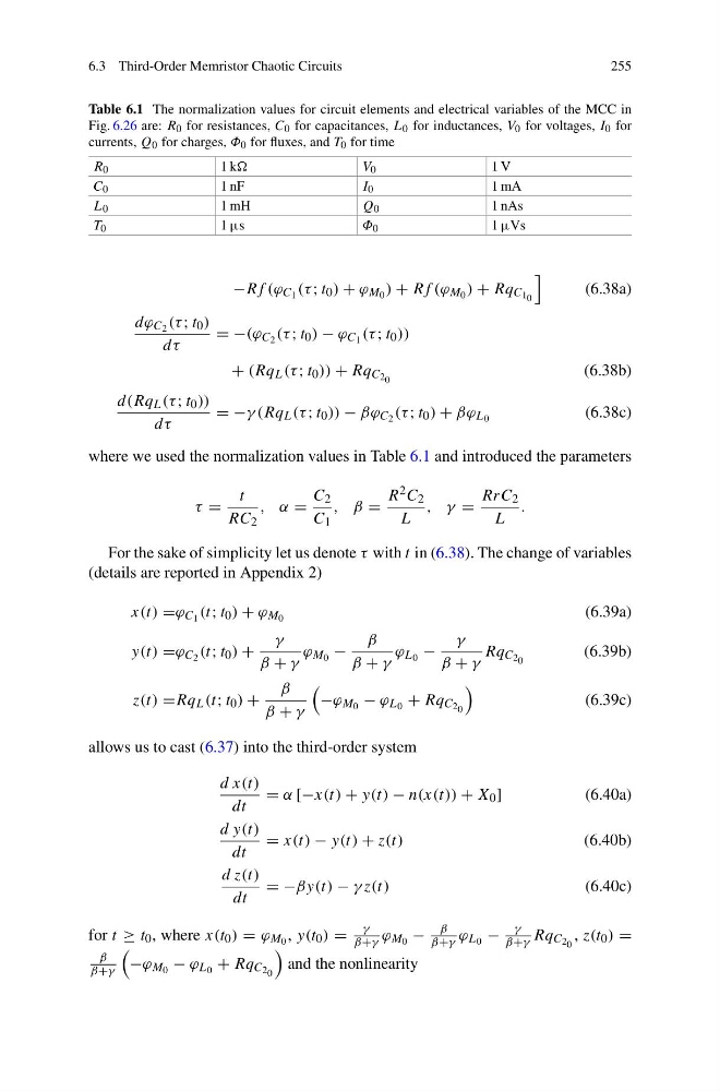
Table 6.1 The normalization values for circuit elements and electrical variables of the MCC in
Fig. 6.26 are: R 0 for resistances, C 0 for capacitances, L 0 for inductances, V 0 for voltages, I 0 for
currents, Q 0 for charges, Φ 0 for fluxes, and T 0 for time
R 0
1 k
V 0
1 V
C 0
1 nF
I 0
1 mA
L 0
1 mH
Q 0
1 nAs
T 0
1 µs
Φ 0
1 µVs
−Rf (ϕ C 1 (τ ; t 0 ) + ϕ M 0 ) + Rf (ϕ M 0 ) + Rq C 1 0
(6.38a)
dϕ C 2 (τ ; t 0 )
dτ
= −(ϕ C 2 (τ ; t 0 ) − ϕ C 1 (τ ; t 0 ))
+ (Rq L (τ ; t 0 )) + Rq C 2 0
(6.38b)
d(Rq L (τ ; t 0 ))
dτ
= −γ (Rq L (τ ; t 0 )) − βϕ C 2 (τ ; t 0 ) + βϕ L 0
(6.38c)
where we used the normalization values in Table 6.1 and introduced the parameters
τ =
t
RC 2
, α =
C 2
C 1
, β =
R 2 C 2
L
, γ =
RrC 2
L
.
For the sake of simplicity let us denote τ with t in (6.38). The change of variables
(details are reported in Appendix 2)
x(t) =ϕ C 1 (t; t 0 ) + ϕ M 0
(6.39a)
y(t) =ϕ C 2 (t; t 0 ) +
γ
β + γ
ϕ M 0 −
β
β + γ
ϕ L 0 −
γ
β + γ
Rq C 2 0
(6.39b)
z(t) =Rq L (t; t 0 ) +
β
β + γ
−ϕ M 0 − ϕ L 0 + Rq C 2 0
(6.39c)
allows us to cast (6.37) into the third-order system
d x(t)
dt
= α [−x(t) + y(t) − n(x(t)) + X 0 ]
(6.40a)
d y(t)
dt
= x(t) − y(t) + z(t)
(6.40b)
d z(t)
dt
= −βy(t) − γ z(t)
(6.40c)
for t ≥ t 0 , where x(t 0 ) = ϕ M 0 , y(t 0 ) =
γ
β+γ ϕ M 0 −
β
β+γ ϕ L 0 −
γ
β+γ Rq C 2 0 , z(t 0 ) =
β
β+γ
−ϕ M 0 − ϕ L 0 + Rq C 2 0
and the nonlinearity
255
Table 6.1 The normalization values for circuit elements and electrical variables of the MCC in
Fig. 6.26 are: R 0 for resistances, C 0 for capacitances, L 0 for inductances, V 0 for voltages, I 0 for
currents, Q 0 for charges, Φ 0 for fluxes, and T 0 for time
R 0
1 k
V 0
1 V
C 0
1 nF
I 0
1 mA
L 0
1 mH
Q 0
1 nAs
T 0
1 µs
Φ 0
1 µVs
−Rf (ϕ C 1 (τ ; t 0 ) + ϕ M 0 ) + Rf (ϕ M 0 ) + Rq C 1 0
(6.38a)
dϕ C 2 (τ ; t 0 )
dτ
= −(ϕ C 2 (τ ; t 0 ) − ϕ C 1 (τ ; t 0 ))
+ (Rq L (τ ; t 0 )) + Rq C 2 0
(6.38b)
d(Rq L (τ ; t 0 ))
dτ
= −γ (Rq L (τ ; t 0 )) − βϕ C 2 (τ ; t 0 ) + βϕ L 0
(6.38c)
where we used the normalization values in Table 6.1 and introduced the parameters
τ =
t
RC 2
, α =
C 2
C 1
, β =
R 2 C 2
L
, γ =
RrC 2
L
.
For the sake of simplicity let us denote τ with t in (6.38). The change of variables
(details are reported in Appendix 2)
x(t) =ϕ C 1 (t; t 0 ) + ϕ M 0
(6.39a)
y(t) =ϕ C 2 (t; t 0 ) +
γ
β + γ
ϕ M 0 −
β
β + γ
ϕ L 0 −
γ
β + γ
Rq C 2 0
(6.39b)
z(t) =Rq L (t; t 0 ) +
β
β + γ
−ϕ M 0 − ϕ L 0 + Rq C 2 0
(6.39c)
allows us to cast (6.37) into the third-order system
d x(t)
dt
= α [−x(t) + y(t) − n(x(t)) + X 0 ]
(6.40a)
d y(t)
dt
= x(t) − y(t) + z(t)
(6.40b)
d z(t)
dt
= −βy(t) − γ z(t)
(6.40c)
for t ≥ t 0 , where x(t 0 ) = ϕ M 0 , y(t 0 ) =
γ
β+γ ϕ M 0 −
β
β+γ ϕ L 0 −
γ
β+γ Rq C 2 0 , z(t 0 ) =
β
β+γ
−ϕ M 0 − ϕ L 0 + Rq C 2 0
and the nonlinearity