

6.1 First-Order Memristor Circuits
229
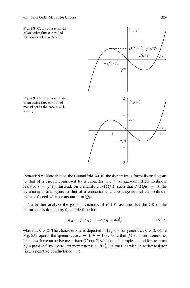
Fig. 6.8 Cubic characteristic
of an active flux-controlled
memristor when a, b > 0
a/3b
−
a/3b
Q
sn
0 =
2a
3
a/3b
−Q
sn
0
ϕ M
f (ϕ M )
Fig. 6.9 Cubic characteristic
of an active flux-controlled
memristor in the case a = 1,
b = 1/3
−2
−1
1
2
−2
−1
1
2
2/3
−2/3
ϕ M
f (ϕ M )
Remark 6.6 Note that on the 0-manifold M(0) the dynamics is formally analogous
to that of a circuit composed by a capacitor and a voltage-controlled nonlinear
resistor i = f (v). Instead, on a manifold M(Q 0 ), such that M(Q 0 ) = 0, the
dynamics is analogous to that of a capacitor and a voltage-controlled nonlinear
resistor forced with a constant term Q 0 .
To further analyze the global dynamics of (6.13), assume that the CR of the
memristor is defined by the cubic function
q M = f (ϕ M ) = −aϕ M + bϕ
3
M
(6.15)
where a, b > 0. The characteristic is depicted in Fig. 6.8 for generic a, b > 0, while
Fig. 6.9 reports the special case a = 1, b = 1/3. Note that f (·) is non-monotone,
hence we have an active memristor (Chap. 2) which can be implemented for instance
by a passive flux-controlled memristor (i.e., bϕ 3
M ) in parallel with an active resistor
(i.e., a negative conductance −a).
229
Fig. 6.8 Cubic characteristic
of an active flux-controlled
memristor when a, b > 0
a/3b
−
a/3b
Q
sn
0 =
2a
3
a/3b
−Q
sn
0
ϕ M
f (ϕ M )
Fig. 6.9 Cubic characteristic
of an active flux-controlled
memristor in the case a = 1,
b = 1/3
−2
−1
1
2
−2
−1
1
2
2/3
−2/3
ϕ M
f (ϕ M )
Remark 6.6 Note that on the 0-manifold M(0) the dynamics is formally analogous
to that of a circuit composed by a capacitor and a voltage-controlled nonlinear
resistor i = f (v). Instead, on a manifold M(Q 0 ), such that M(Q 0 ) = 0, the
dynamics is analogous to that of a capacitor and a voltage-controlled nonlinear
resistor forced with a constant term Q 0 .
To further analyze the global dynamics of (6.13), assume that the CR of the
memristor is defined by the cubic function
q M = f (ϕ M ) = −aϕ M + bϕ
3
M
(6.15)
where a, b > 0. The characteristic is depicted in Fig. 6.8 for generic a, b > 0, while
Fig. 6.9 reports the special case a = 1, b = 1/3. Note that f (·) is non-monotone,
hence we have an active memristor (Chap. 2) which can be implemented for instance
by a passive flux-controlled memristor (i.e., bϕ 3
M ) in parallel with an active resistor
(i.e., a negative conductance −a).